1984 ODOMETER REPAIR PROCEDURE
While I was driving
I took a couple of pictures (of course) and thought I'd share the procedure I
followed with my fellow Newbies that want to make this repair. This repair
applied to the '84 MY but should apply to most if not all the mechanical
odometer MY.
Here's the tools I used to remove the pod:
13mm combination wrench
27mm socket, 6 inch extension, socket wrench
10mm socket
medium Phillips
5mm Allen socket (long)
Here's the tools I used to work on the instrument cluster/odometer:
medium Phillips and small Phillips screwdriver
flat blade screwdriver
7mm nut driver
standard pliers and needle nose pliers
small, thin wire
replacement odometer drive gear (available at www.rennbay.com/-c-32.html)
for about $27.50.
First you will need to remove the pod in order to remove the instrumentation
cluster. In a previous post I included a procedure for fully disassembling the
pod in order to remove it. However, in this procedure, we'll follow a shortcut
to getting at the instrumentation cluster without fully disassembling and
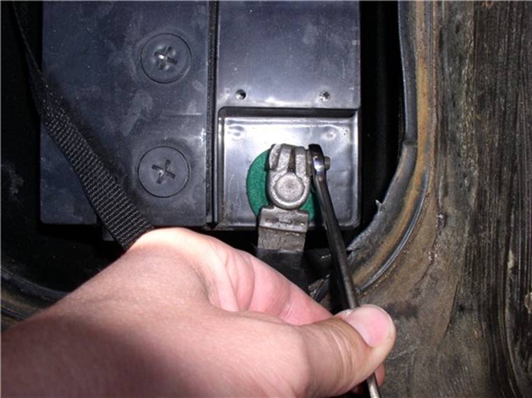
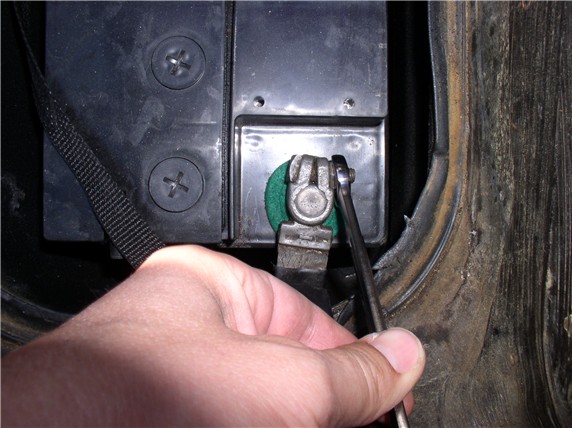
removing the pod making this procedure considerably easier. First, disconnect
the negative battery terminal using the 13mm combo wrench.
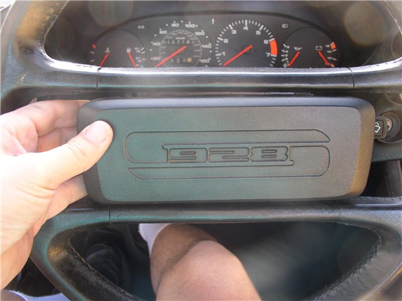
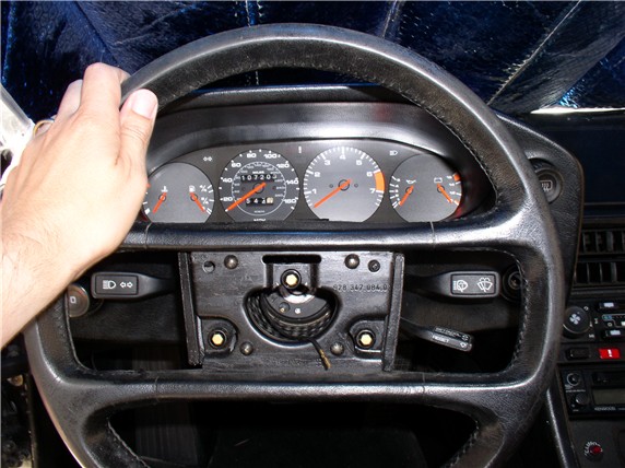
Next, remove the horn pad by gripping it on both ends with your hands and
giving if a firm tug toward you. There are 3 clips
that hold the horn pad to the wheel (one on top-center and 2 on the bottom half
(left and right)). Use "shallow" but firm tugs. There is a horn wire
connected to the back of the pad and you don't want to violently pull the pad
off the wheel and damage the wire/connector.
After the horn pad is off, disconnect the horn wire.
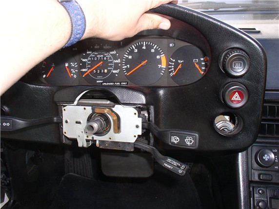
Next, use the 27mm socket and extension to loosen and remove the nut that
secures the steering wheel to the steering column. I've had good luck simply
holding the steering wheel firmly with my left hand while using my right to use
the wrench. It's best to NOT use the steering wheel locking mechanism to hold
the steering wheel in place while you loosen the nut - the force could damage
the locking mechanism. If you can't hold the steering wheel with one hand, a
helper may be able to hold the steering wheel in place while you loosen the nut.
Do not remove the nut completely from the steering column threads. By leaving
the nut on the column, it will act as a safety stop when you pull the steering
wheel off the column and keep the steering wheel from hitting you in the face.
Before pulling the steering wheel off the steering column, center the steering
wheel as perfectly as you can so you can easily orient the steering wheel in
the same location when putting it back on. Then give the steering wheel a good
firm tug toward you to remove it. When loose, take the nut off the column and
remove the wheel.
Lower the tilt wheel paddle.
Then remove the two phillips screws that hold the
underpod cover plate in place. There's one on the left, and.....
....one on the right.
The underpod cover plate is removed by sliding it toward the front of the car
in order for the tab/prongs to clear. You can see the tabs indicated by the arrow
in the picture below. These tabs can easily break off if forced down without
pulling the plate forward.
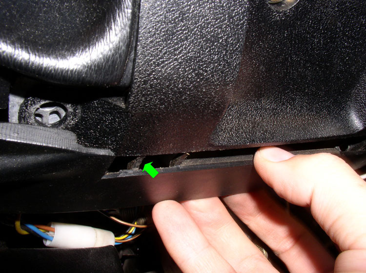
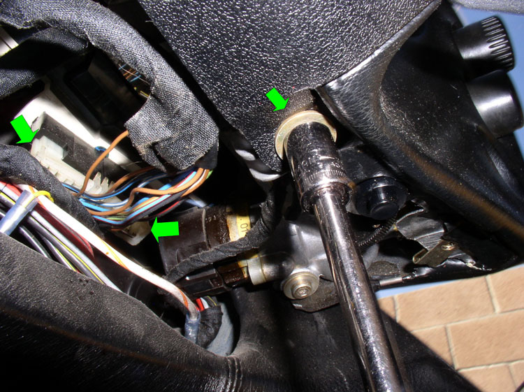
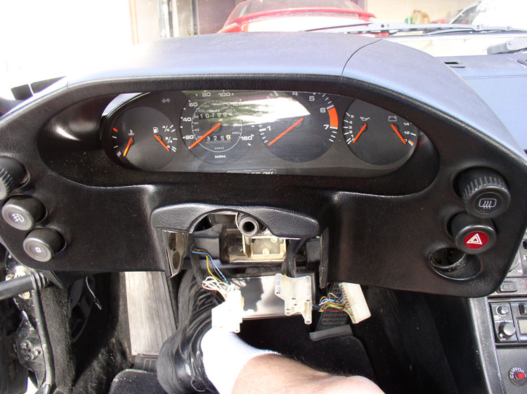
Next, remove the two 10mm bolts that secure the signal/wiper/cruise cluster
cover as indicated by the great arrow. There's one bolt on the right and one on
the left of the signal/wiper/cruise cluster. By now you may also notice the
electrical harness connector to the instrumentation cluster underneath
(indicated by the 2 green arrows). There should be a harness connection on the
left and one on the right underneath the pod. We will disconnect these shortly.
Remove the Phillips screw from the signal/wiper/cruise cluster cover and...
....remove the cover.
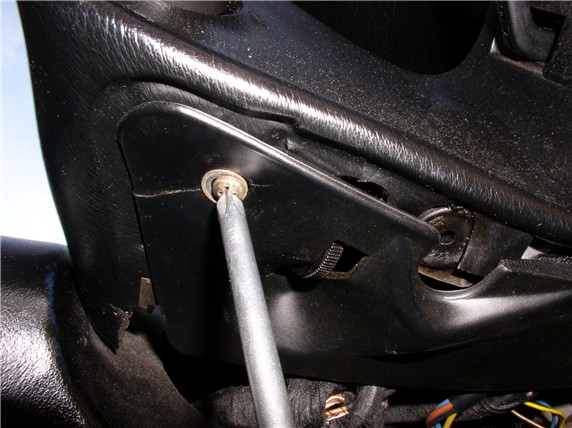
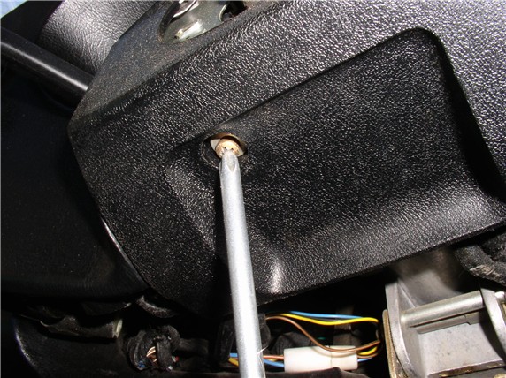
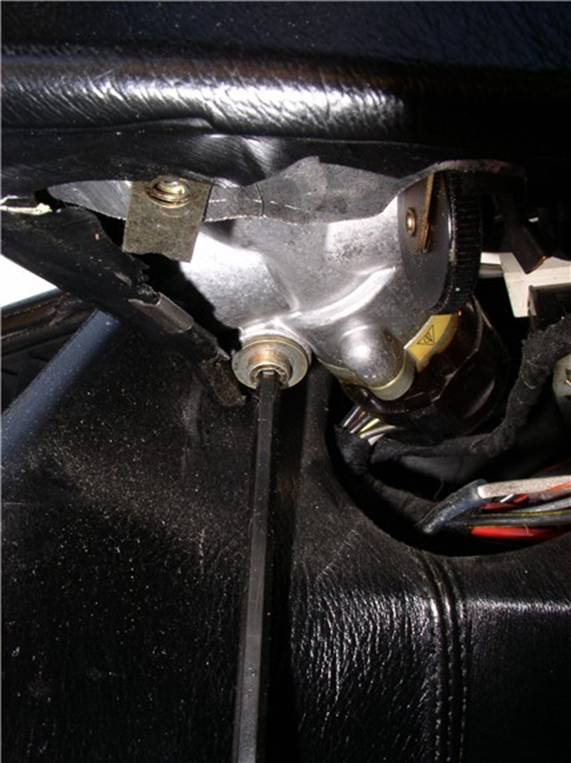
Next, remove the right Allen head bolt that secures the pod
to the dash framework. It's located to the right and underneath the pod (underneath
the ignition switch module). I used a 5mm Allen socket (long).
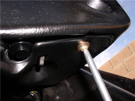
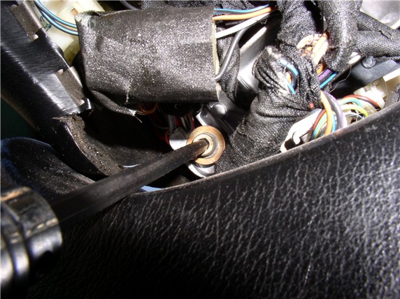
Remove the Allen bolt on the left underneath the pod.
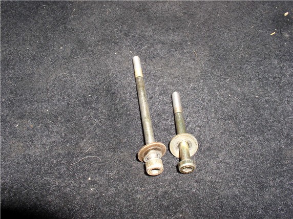
Note that the long bolt is used on the left side and the short bolt on the
right.
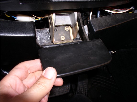
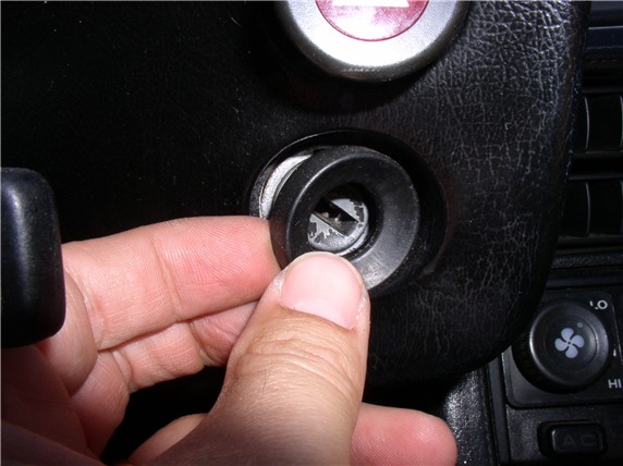
Remove the rubber grommet around the ignition switch. You can use a flat blade
screwdriver to assist with the removal.
Next, we need to remove the signal/wiper/cruise cluster from the steering
column. But first we need to maneuver the pod so the cluster will clear. Start
by pulling the pod forward enough to clear the ignition switch. Then lift the
pod slightly - enough so the signal/wiper/cruise cluster will clear the pod.
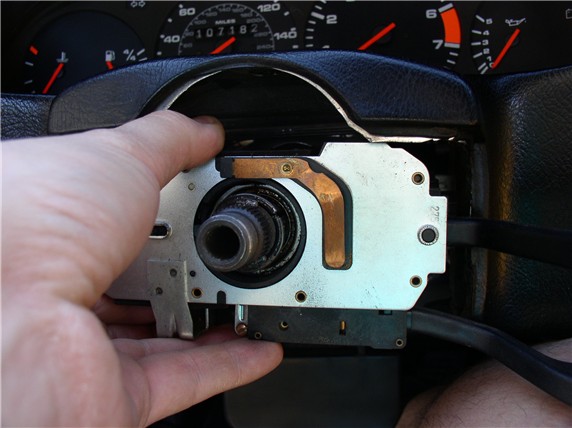
While holding the pod up with one hand, use the other to grasp the
signal/wiper/cruise cluster and twist while pulling toward you. Eventually, it
will begin to work free and move toward you. I noticed on my cluster that there
is a place for a clamping bolt to hold it in place on the steering column.
However, no bolt was in place. If yours has a clamping bolt in place, you will
need to loosen it in order to move the cluster. Move the cluster forward on the
column enough so you can reach behind the cluster and disconnect the two wiring
harnesses.
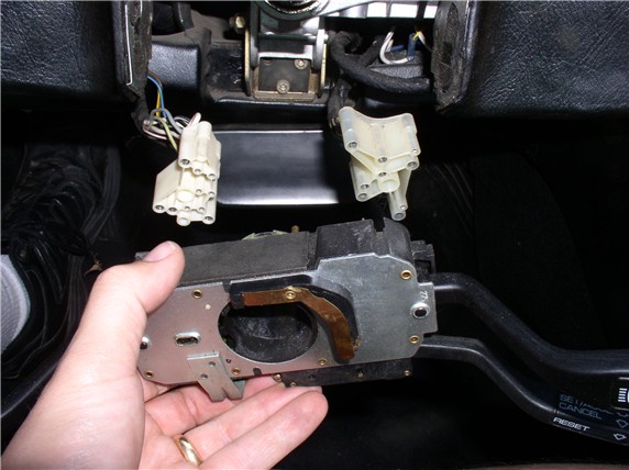
Once, you've detached the harness connectors, you will be
able to remove the cluster from the steering column. The cruise wire
connector (a small barrel connector) is still connected but you can leave that
in place and let the cluster hang down.
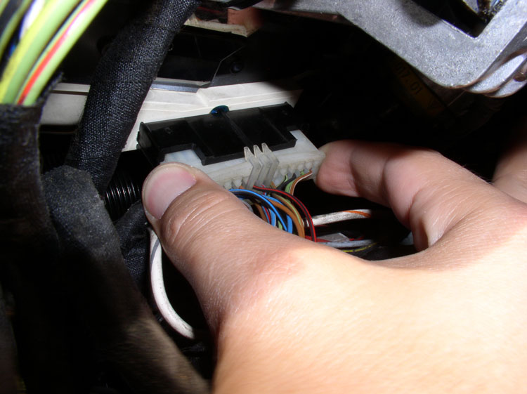
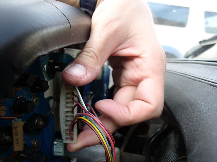
Next, disconnect the instrumentation cluster wiring harness leads from
underneath the pod. These were pointed out earlier with the green arrows.
There's a connector on the left of the pod and one on the right. Disconnect
both of these by grasping the ends of the connector and rocking the connector
side to side while pulling down. You can remember the orientation by the
plastic locking clips (shown on top of the harness lead in the photo).
Then, move the pod slightly forward enough to get behind it and disconnect the
third and final harness lead.
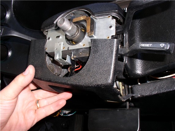
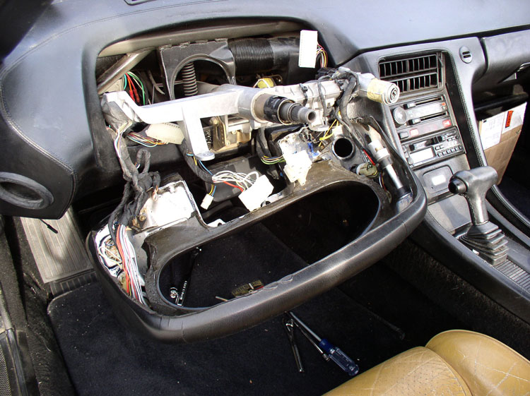
Pull the pod forward enough to just clear the end of the steering column...
...and rotate the pod downward as shown in the picture.
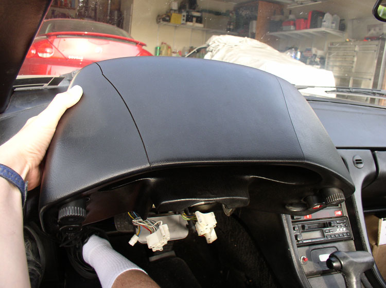
Continue to rotate it downward until it is facedown in your lap.
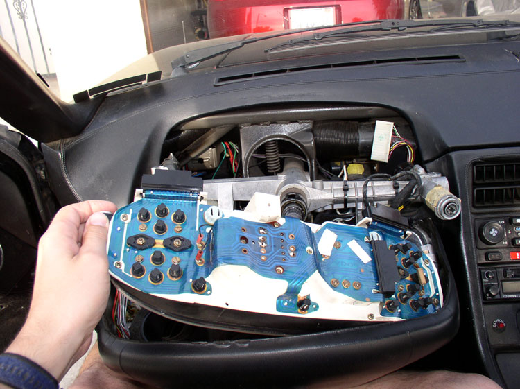
Now you are ready to remove the instrumentation cluster from the pod. The left
side of the cluster should be free to move upward. Begin by lifting the left
side of the cluster upward as shown in the picture. You will notice there are
two aluminum/rubber bushings/guides for the securing Allen head bolts attached
to the end of the instrumentation cluster. You can leave these in or take them
out and put them in a safe place (remember their orientation - rubber ends to
the outsider).
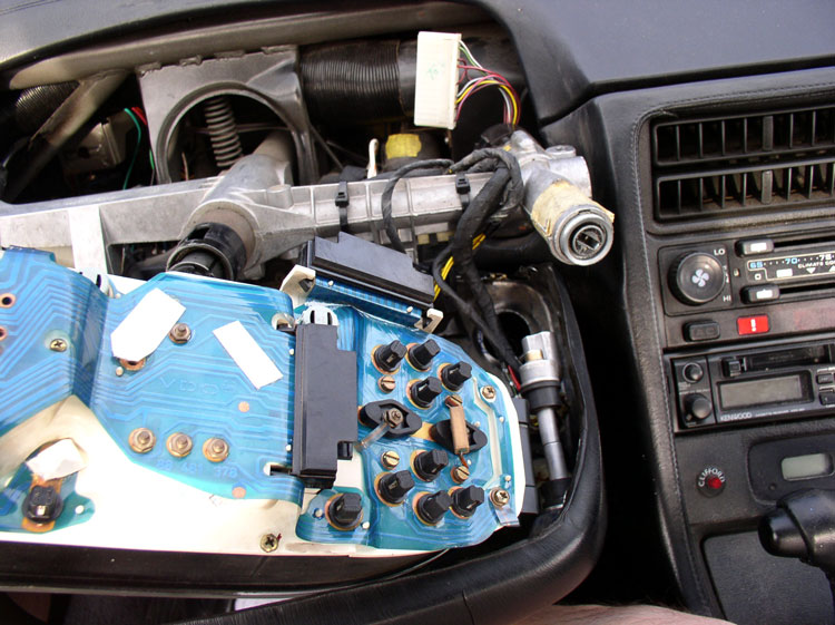
Next, you can simply pull the instrument cluster to the
right and away from the bushing/guides as pictured. You will notice the right
side bushing/guides are secured to the pod by another 5mm hex bolt. You can
leave this in place as it will be easier to reassemble the cluster back into
the pod.
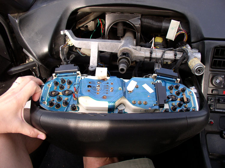
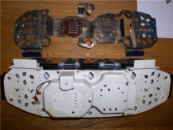
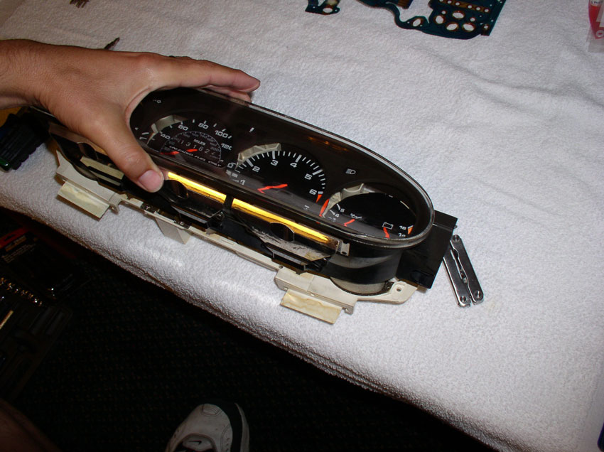
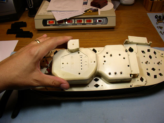
You should now have the instrument cluster separated from the pod.
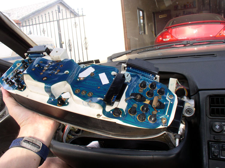
You can let the pod hang where it is or set it back up on the steering column.
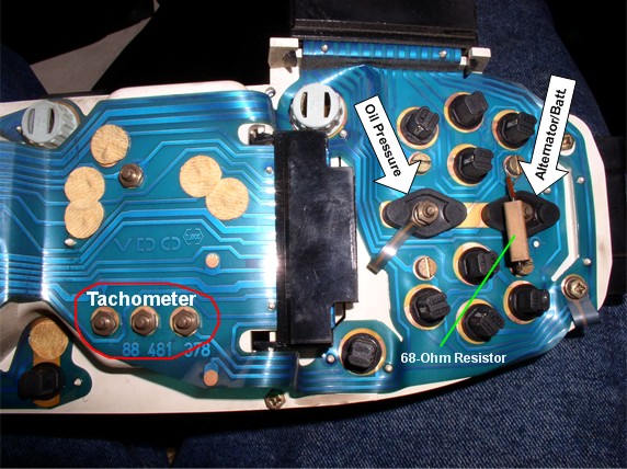
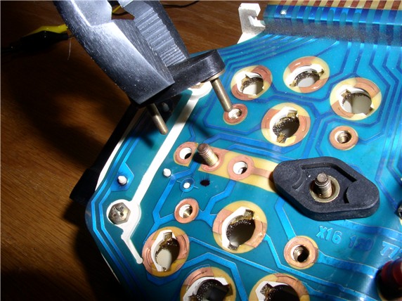
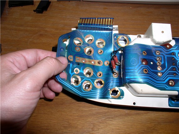
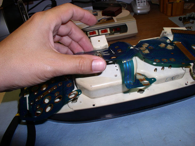
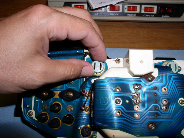
On the right side of the cluster you can see the contacts/securing nuts for the
alternator gauge, oil pressure gauge and tachometer as pictured.
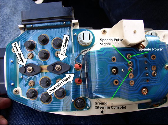
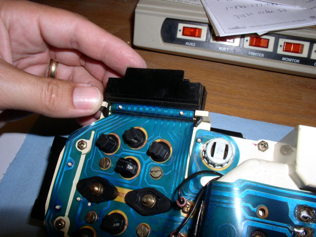
On the left side, you can see the temperature gauge, fuel gauge,
odometer reset contacts, speedometer pulse signal, power, and ground contacts.
I had to clean and solder the speedometer contacts last summer when my
speedometer quit working.
At this point, you have a couple of choices to proceed depending on your
situation. If your only objective is to repair the odometer, you can take a
shortcut to remove the speedo/odo unit only. If you have some cleaning to do on
the instrument contacts etc., you can remove the printed plastic circuit board
from the instrument cluster to clean/solder and then remove the speedo/odo unit.
I've included both options in this post. First, the shortcut.
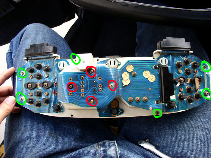
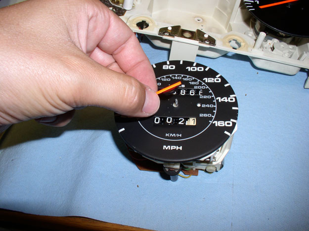
In order to remove the speedo/odo unit, you will remove the plastic front cover
of the instrument cluster since the speedo/odo unit must be removed from the
front. You will remove the Phillips screws circled in green in the picture
below. I only had 6 of the screws to remove. Your cluster may have more.
Second, the spedo/odo unit is secured using 4 small Phillips screws circled in
red in the picture below. remove these 4 screws using
the small Phillips screwdriver. Then, turn the cluster over with gauges facing
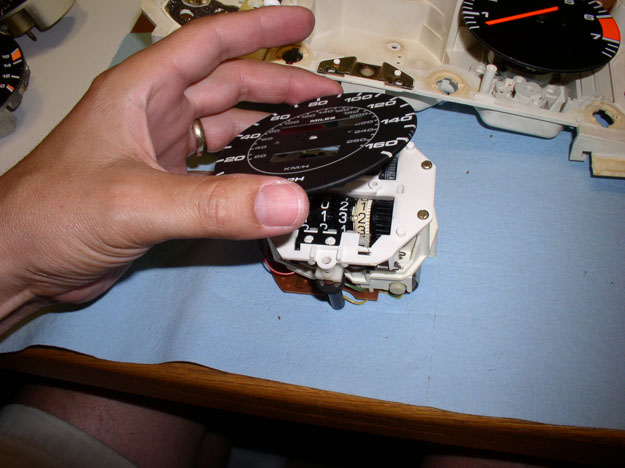
up and pull the plastic face cover off. Then, pull the speedo/odo unit upward,
rocking gently side to side while pulling up. Then jump to post #13 of this
thread to continue on with the repair procedure.
If you want to remove the plastic circuit board follow these steps. Remove all the
small warning lights. These rotate 90 degrees counterclockwise then pull up and
out.
Then, remove the larger 3 instrument board lights. These also rotate 90 degrees
counterclockwise and pull up and out.
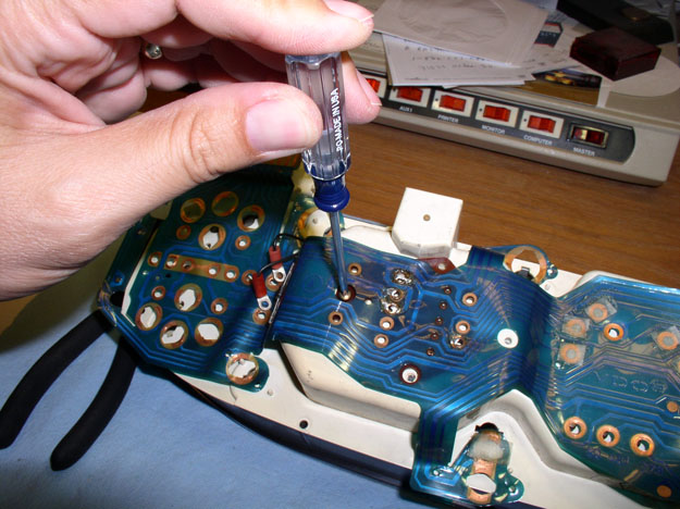
Next, using the flat blade screwdriver, remove the gauge contact screws. There
are 2 per gauge for a total of 8.
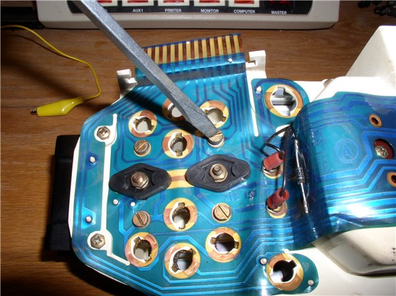
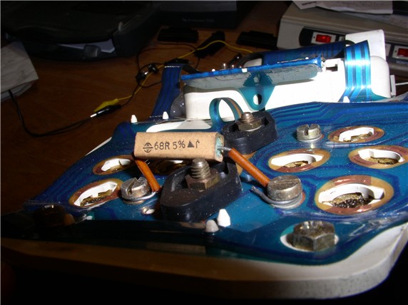
You will notice a 68 ohm resistor on the contact screws for the alternator
gauge. Remove this as well when you take the screws out.
Next, using the 7mm nut driver, remove the center nut at the back of each gauge
as pictured.
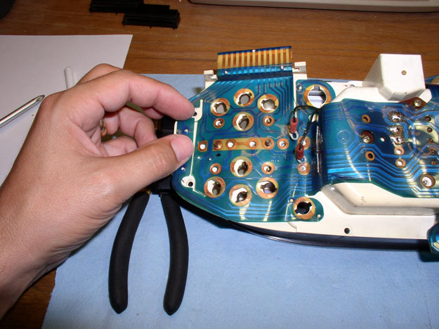
You can then pull up on the plastic plug fitting using a pair of pliers as
shown.
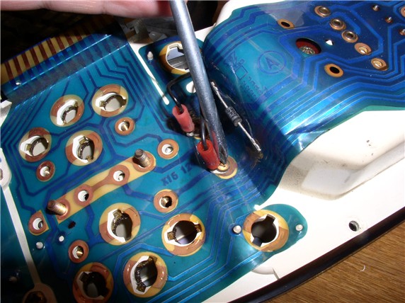
Next, use the 7mm nut driver to remove the contact nuts for
the tachometer as shown.
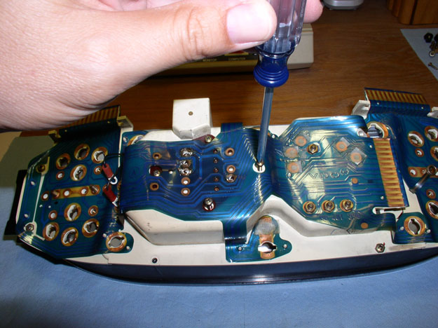
Then, remove the two Phillips screws that secure the odometer reset wires.
Next, you can remove the two Phillips screws that secure the speedo hard
circuit card to the instrument housing. One here as shown...
and the other one here.
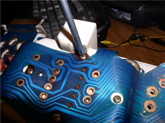
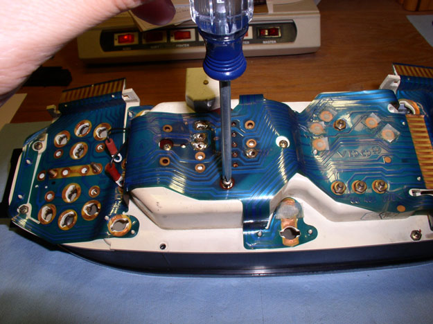
There is also one Phillips screw securing the printed plastic circuit board to
the instrument housing. Remove that screw as well.
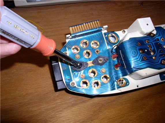
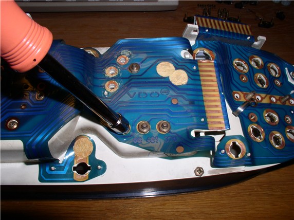
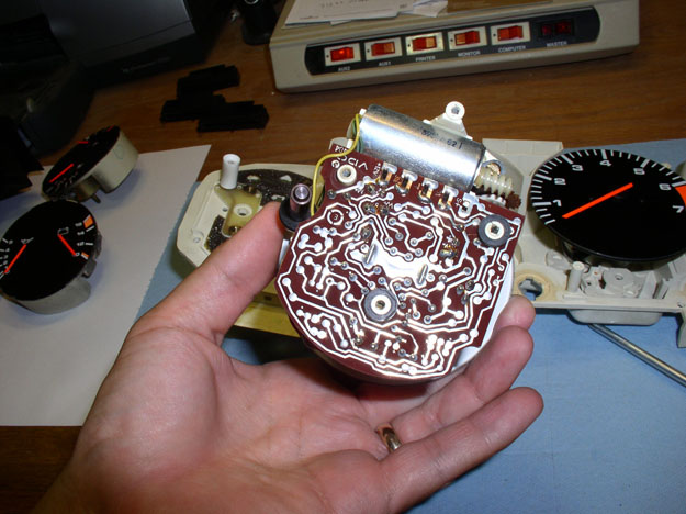
At this point, the printed plastic circuit board can be removed for cleaning or
additional inspection. Start at one end and gently pull the printed plastic
material up around the small plastic locating posts that hold it in place.
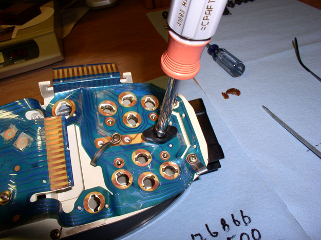
When you get to the speedo/odo unit (the hard circuit card),
you can gently pry the hard card up with a flat blade screwdriver as shown.
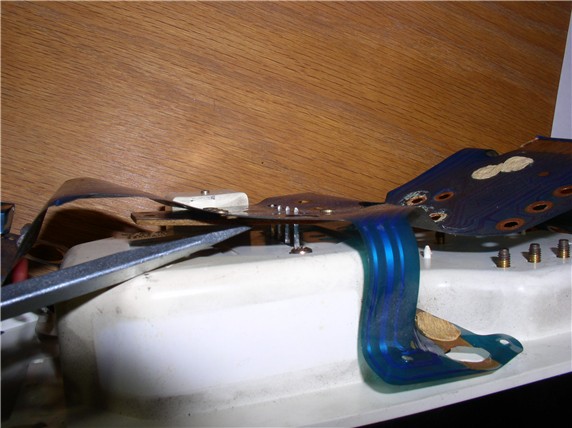
Continue removing the plastic material from the locating posts and the plastic
circuit board will be removed. You can work on it separately, if needed.
To continue on with removing the speedo/odo unit, remove the phillips
screws that secure the instrument cluster face plate to the instrument housing.
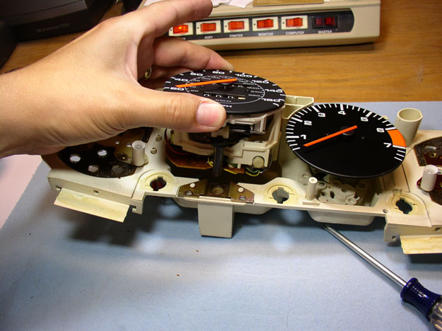
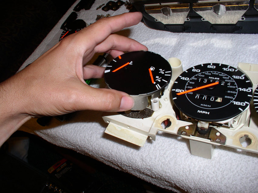
After removing all of the face plate screws, turn the instrument cluster over
so gauges are facing up and lift off the face plate. The gauges should be
exposed as shown.
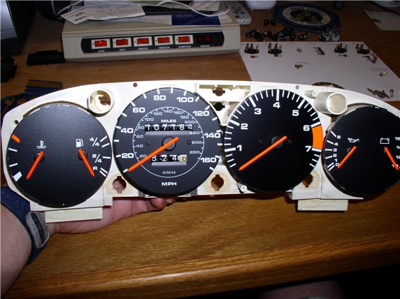
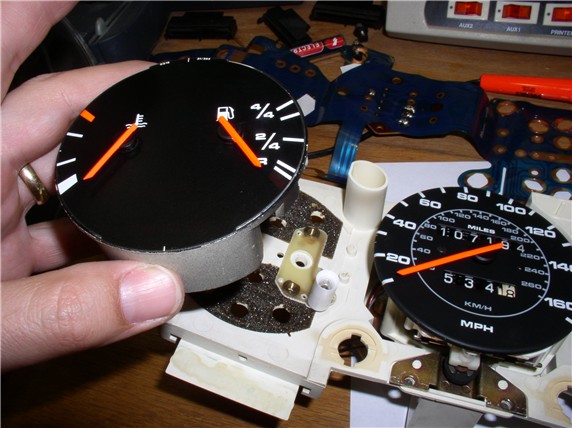
You should be able to remove the temp/fuel gauge and the alternator/oil
pressure guage by simply lifting up on them as shown. You can
inspect/clean/repair these, if needed.
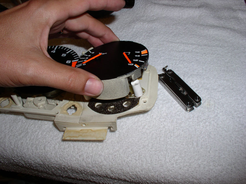
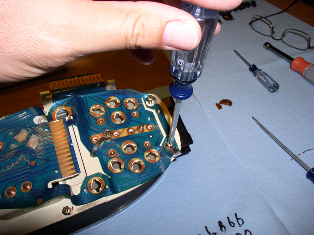
Now turn the instrument cluster on the side as shown and remove the two small Phillips
screws that secure the speedo/odo unit to the instrument housing.
Second screw.
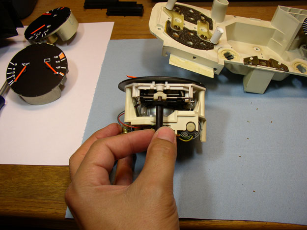
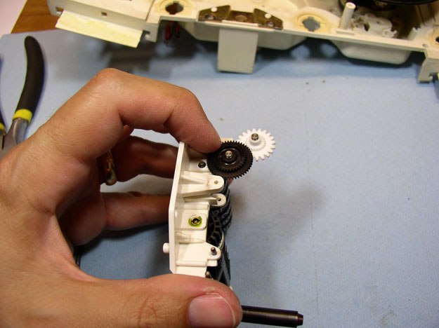
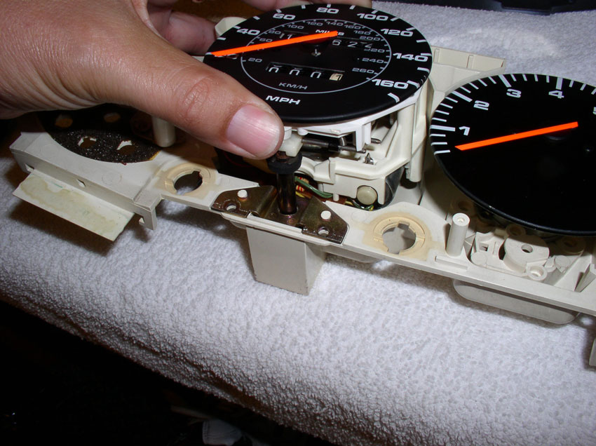
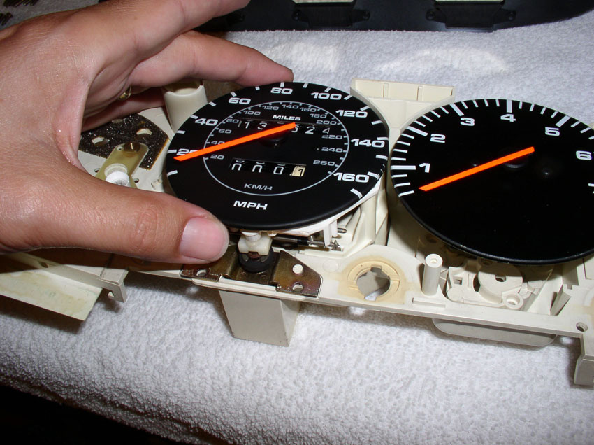
After the screws are removed, you can carefully lift up/pull out the speedo/odo
unit as shown.
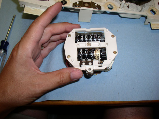
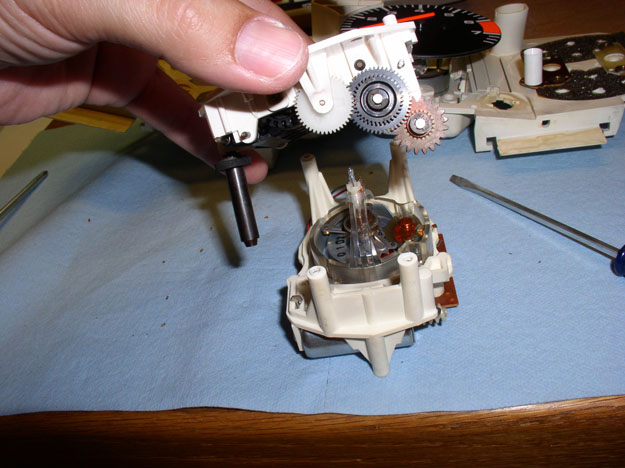
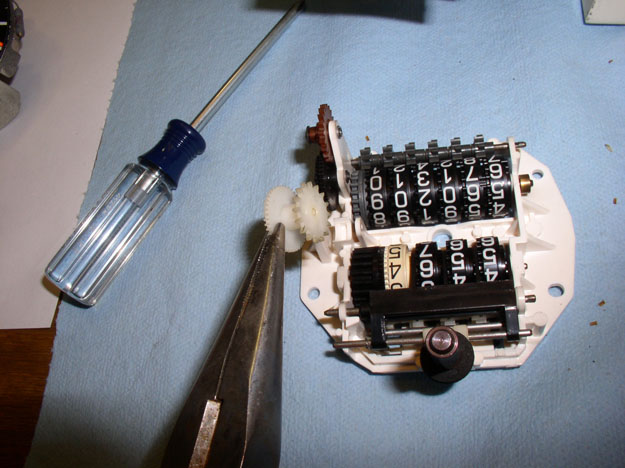
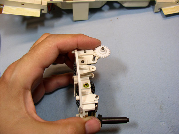
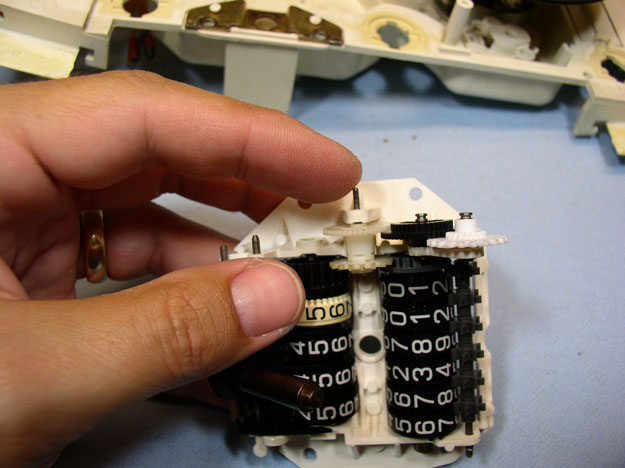
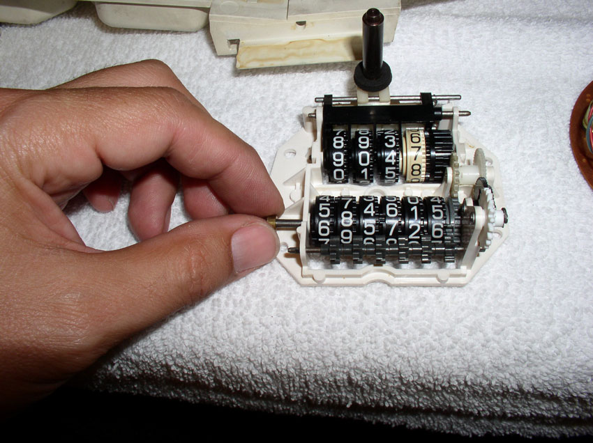
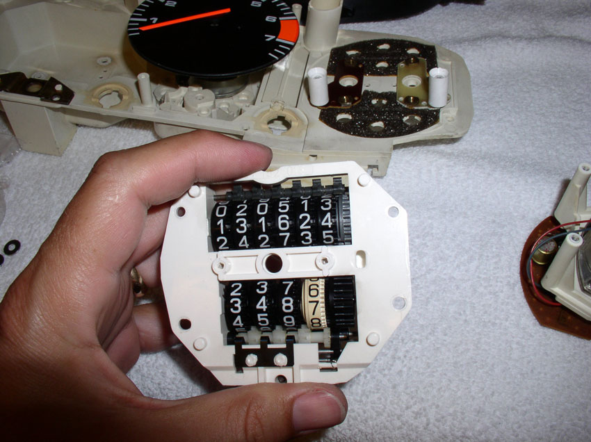
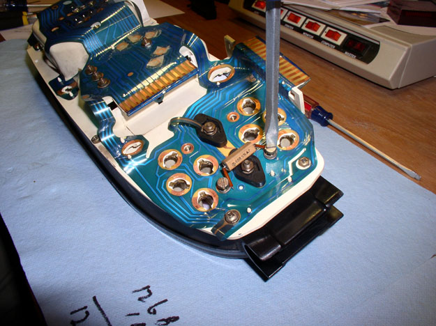
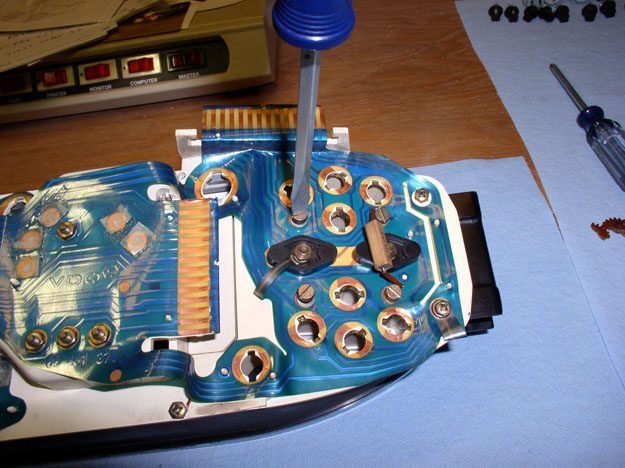
Inspect the unit for any obvious issues/damage. This inspection will also give
you an idea what it should look like when you put it back in.
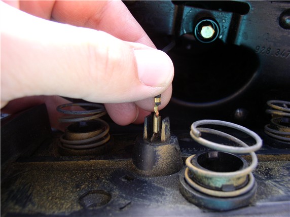
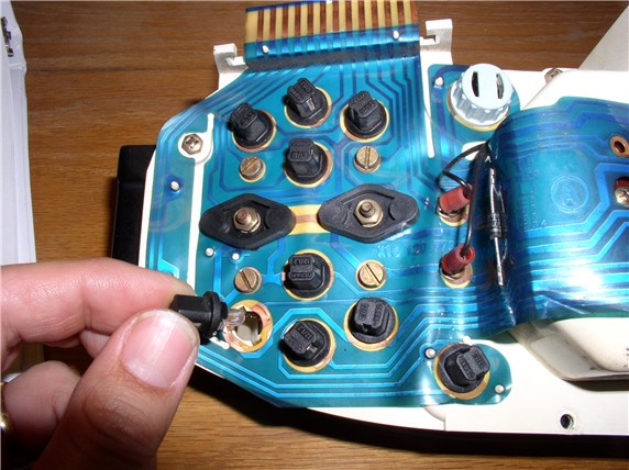
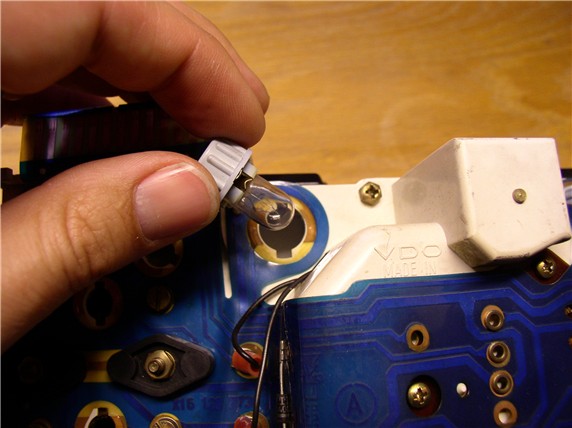
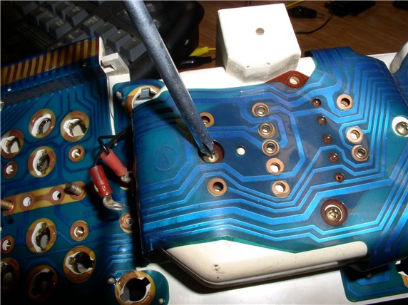
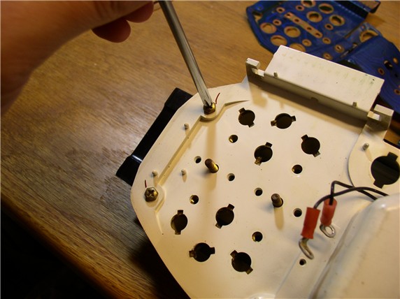
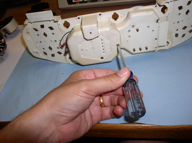
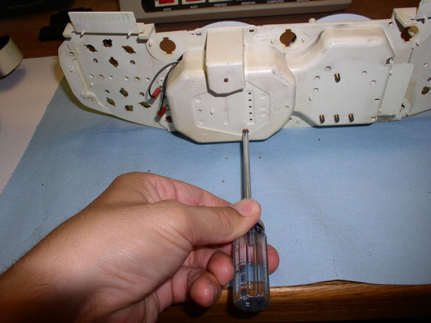
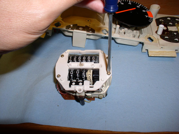
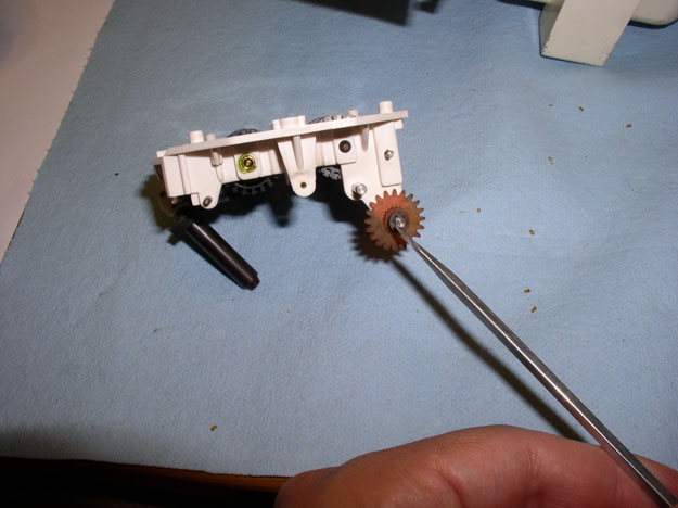
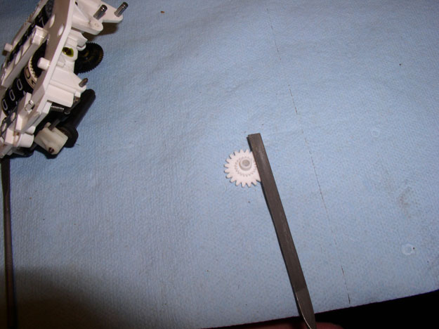
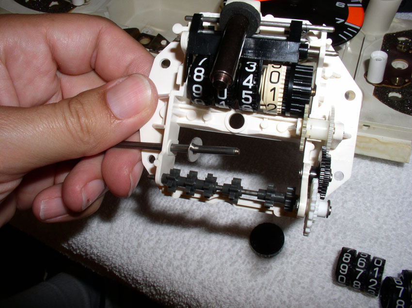
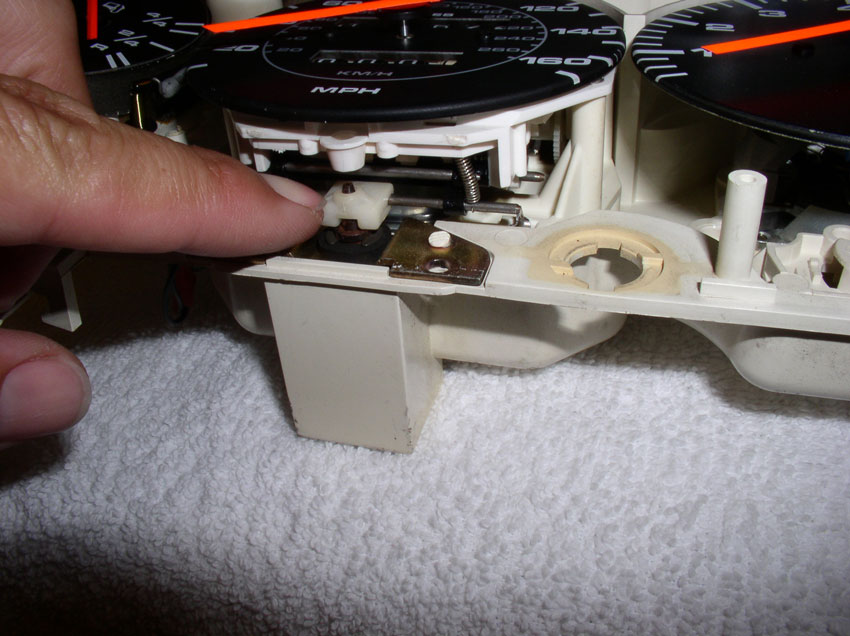
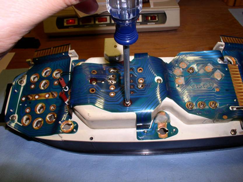
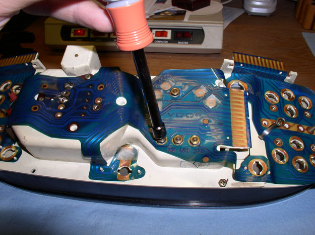
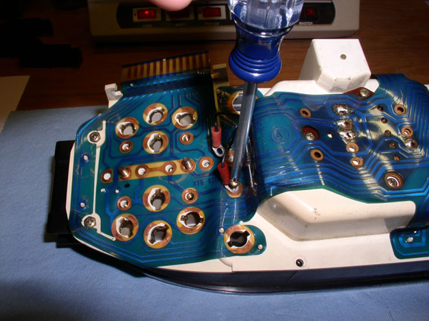
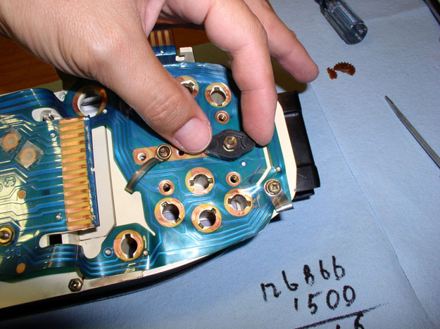
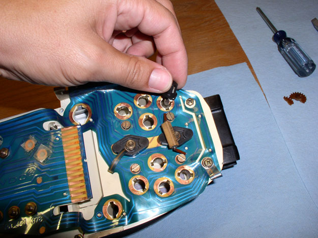
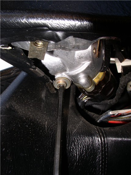
The odometer reset works on an electro magnet mechanism. You
can pull down on the cylinder as shown and it will manually reset the odometer.
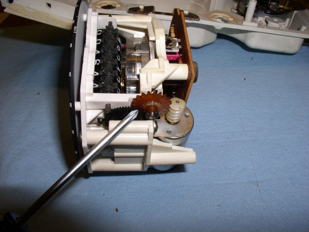
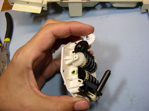
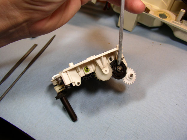
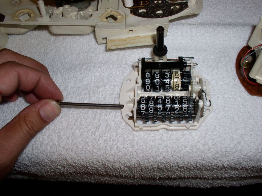
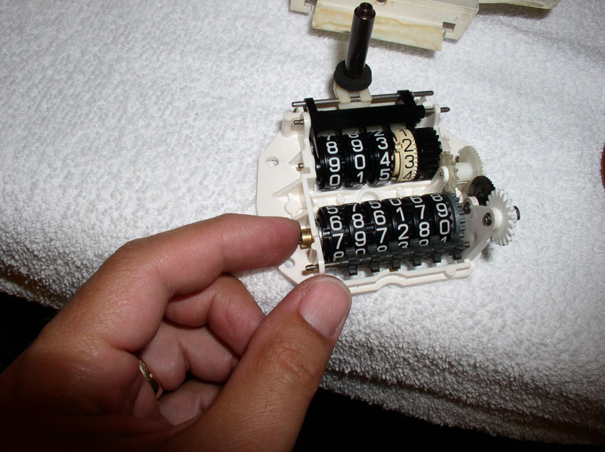
The odometer gear pointed at by the screwdriver is the one that failed. The
gear has a set of outer teeth that interlock with the worm gear of the drive
motor as shown. The inner teeth, interlock with the next gear wheel. Because
the first gear is prone to becoming brittle with age, when it encounters
resistance (such as the odometer tumblers locking due to excessive gap between
the tumblers), it can strip the inner gear teeth off. Such as
the case with mine.
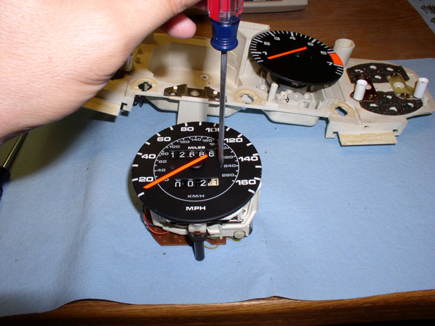
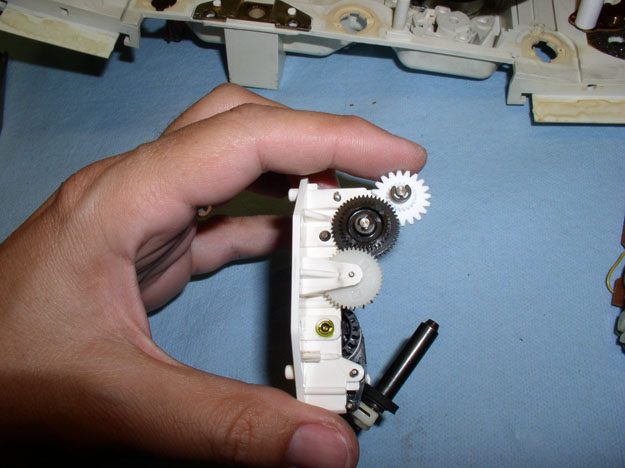
In order to replace the failed gear, I disassembled the speedo/odo unit. First,
you'll need to remove the face plate in order to get at the housing screws.
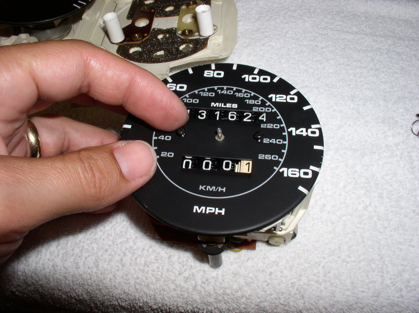
Before removing the face plate and needle, make special note of where the
speedometer needle is oriented on the face plate. At rest, my needle lined up
directly over the first line/mark of the speedometer facing. You'll want to
re-install the needle later in the exact same position. You can remove the two
small face plate screws as shown.
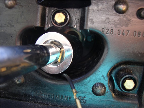
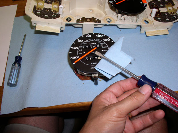
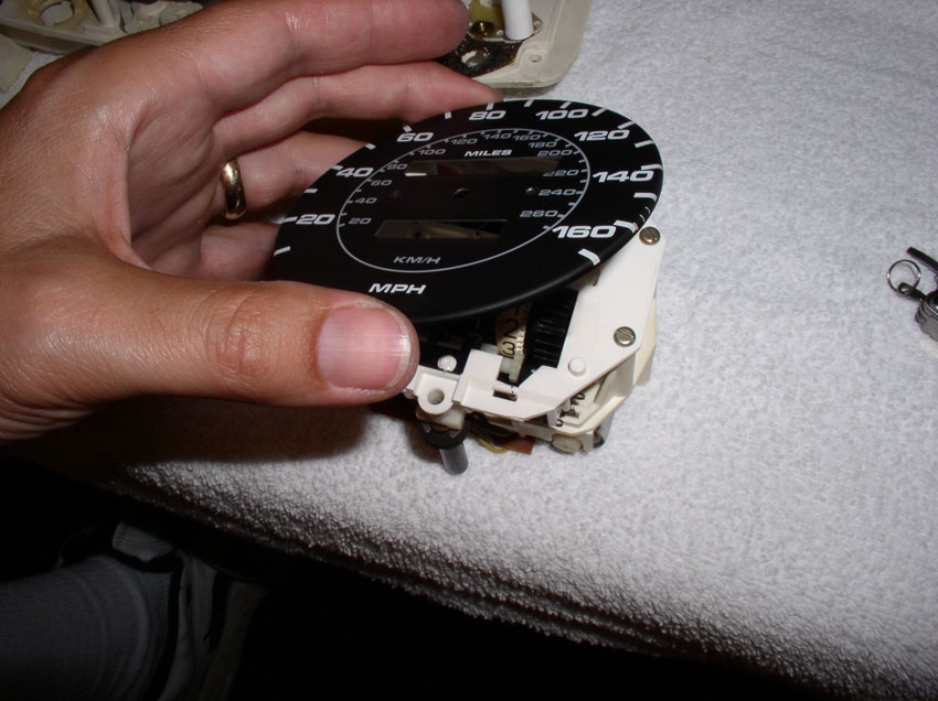
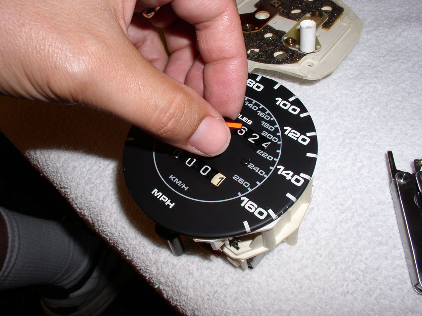
You'll need to remove the needle in order to remove the face plate. The speedo
needle is press fitted on a small spindle with fine gear teeth on the end. It
needs to be pried off carefully. You can use a flat blade screwdriver for this.
Make sure you place a cloth or towel under the screwdriver to protect the
finish on the speedo face plate. I applied a constant force with the
screwdriver with one hand while grasping the black center plastic needle hub
with the other hand and gently rocked it back and forth until it began to move
free. Do not try to lift up the needle by the orange part. It is very easily
bent.
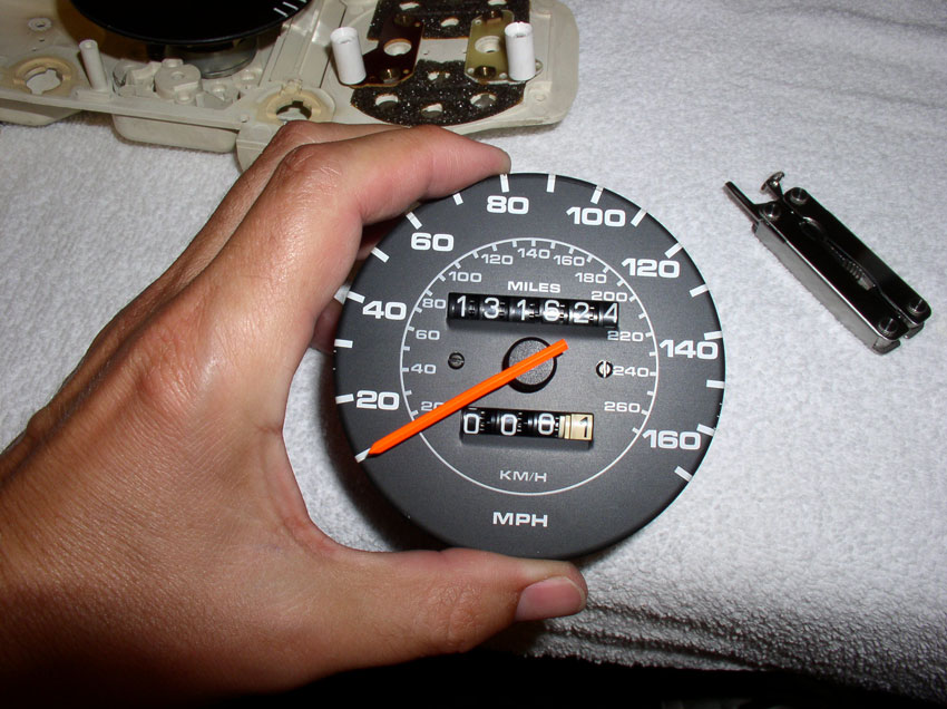
Once the needle is free, remove it and set it aside.
Now the face plate will come off as shown.
There are 4 small flat blade screws that hold the two halves of the unit
together.
Remove the 4 screws in order to separate the mechanical half with tumblers from
the electronics half.
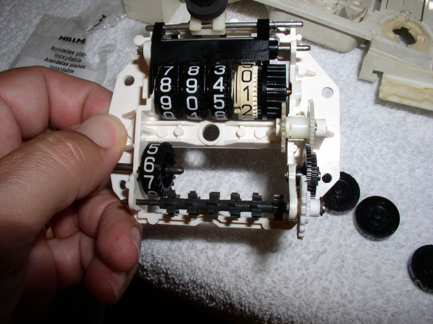
After the screws are removed, carefully separate the two halves by lifting up
on the odo tumblers section as shown.
I needed to remove two gears in order to get at the failed gear. To remove the
drum gear, I used a small thin wire to "push out" the gear pin
holding the gear in place.
Once the gear pin is partially out, grasp it with some needle nose pliers...
...and remove it. Set is aside on a clean paper towel or other organized parts
collection area.
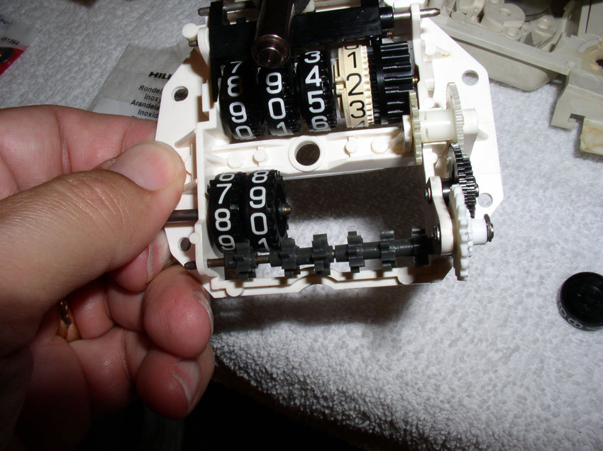
After the pin is removed, you can grasp the drum gear with the needle nose
pliers as shown and remove.
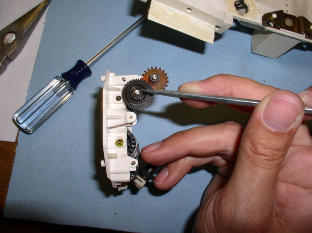
Next, you will need to remove the black intermediate gear. This gear and the
first gear are held in place by a very small circlip. I used a small flat blade
screwdriver to pry off the clip. Be very careful when prying the clip off as it
can fly off and get lost. To prevent loss of the clip, I cupped my hand over
the gear while prying.
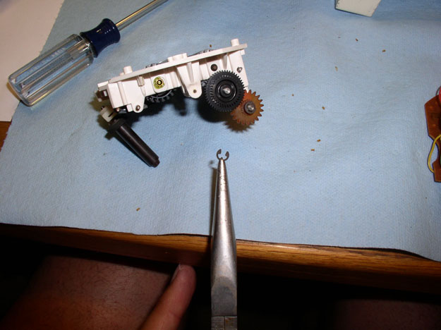
Here's a pic of the clip when removed.
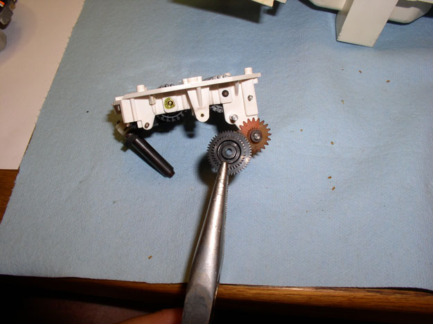
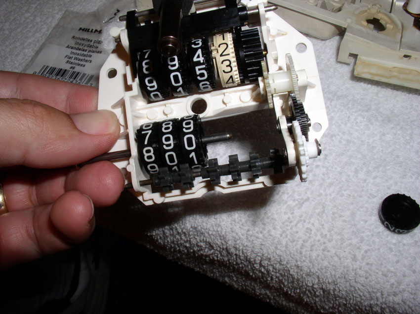
After the clip is removed, you can remove the black intermediate gear as shown.
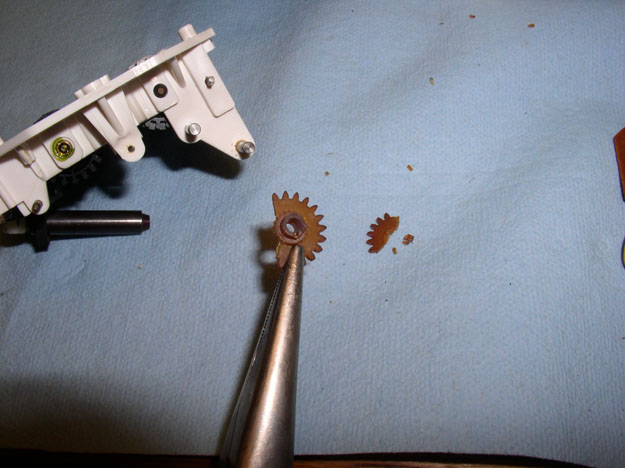
Next, remove the circlip from the first gear wheel in the same manner as the
intermediate gear.
Then remove the gear. Unfortunately, my gear was so brittle,
it broke while I was removing the clip.
Here's the old gear compared to the new (white) gear I purchased from Rennbay.
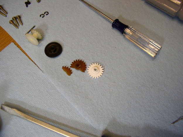
The new gear had some plastic "flash" left over from the molding
process on one of the outer gear teeth. Use a small file to file down/remove
any flash or rough edges left over from the molding process.
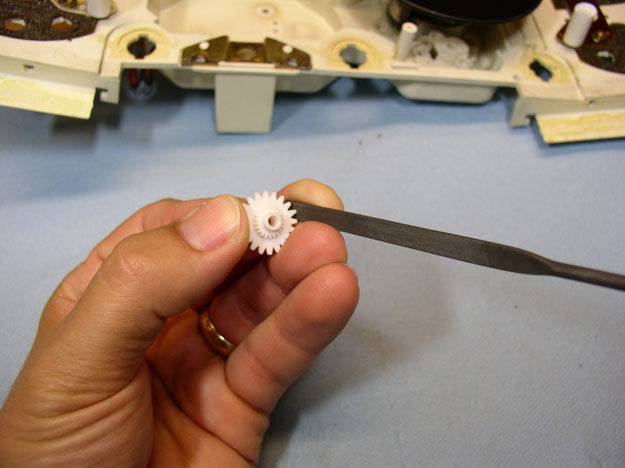
The new gear also had 3 small raised "knots" on the flat surface that
mated with the intermediate gear. I assume these were also remnants from the
molding process. It is very important these protrusions be filed down level
with the flat surface of the gear. If not, they will catch on the intermediate
gear and hang (i.e., stop the odometer from working again).
Once you are satisfied all surfaces are flat and smooth, place the gear on the
odometer and spin with your finger checking for smooth operation. Now is an
excellent time to also look for and clean any debris remaining from the old
torn up gear. If there are small pieces of debris from the old gear falling
apart left in the odometer tumblers or any of the gears, they can lock up the
odometer. Inspect all gears, housing and tumblers for old gear debris while
re-assembling the unit. We'll be inspecting the tumblers later when we remove
them.
Next, set the black intermediate gear in place and again check for smooth
operation. It took me two or three attempts at filing the "knots" off
in order to get it perfectly smooth enough to pass this test.
Then, you can insert the drum gear as shown.....
....and insert the drum gear pin as pictured below.
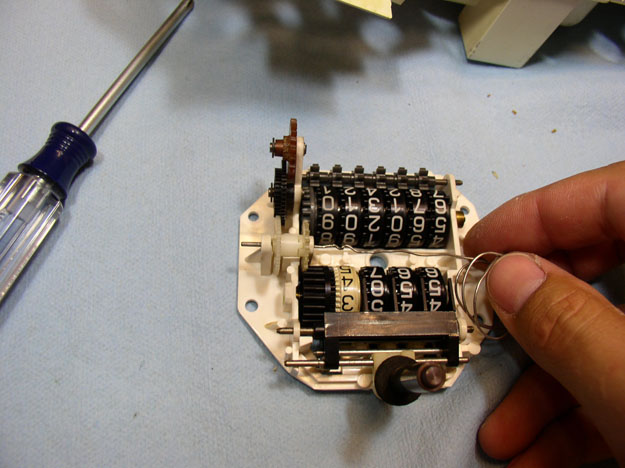
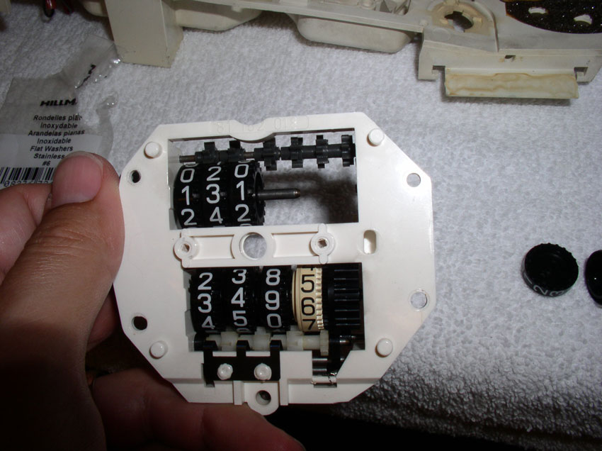
Now, check again for smooth operation. At this point, the odo tumblers should
move as well.
Re-install the small circlips on the intermediate gear and the first gear.
And check again for smooth operation. It was at this point I noticed that there
was significant gap between my odo tumblers and if two tumblers were pushed
apart, the gap was sufficient to "lock up" the odometer and prevent
it from moving. The total gap between my tumblers appeared to be just under 1mm. Therefore, I would guess that if the total gap is
more than 0.5mm, it is probably enough to cause the odometer to lock up under
the right conditions. We'll look at removing the "gap" in the next
set of steps.
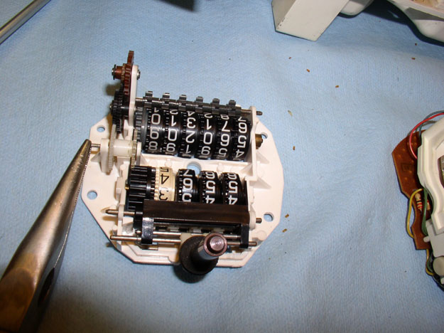
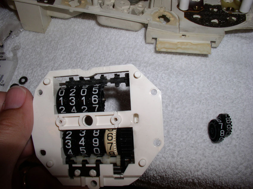
In these next steps, we'll be taking out the odo tumblers to insert a small
washer to take out the gap/slack between the tumblers. This is also an
excellent time to correct/add any missing miles that resulted from the car
being driven with the odometer not working. Fortunately, I had a good idea of
exactly how many miles were missing due to the failed odometer. First, we need
to remove the tumblers. Grasp the tumbler shaft/pin by the end and pull outward
as shown.
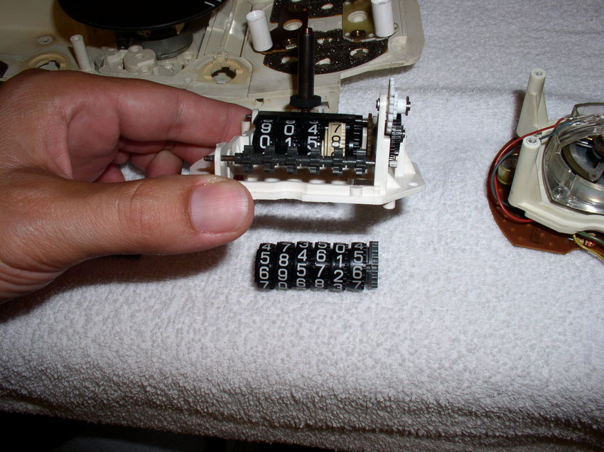
Fully remove the shaft/pin while the tumblers are face down on the table as
shown.
Then lift the odometer assembly and the tumblers should remain on the table as
shown.
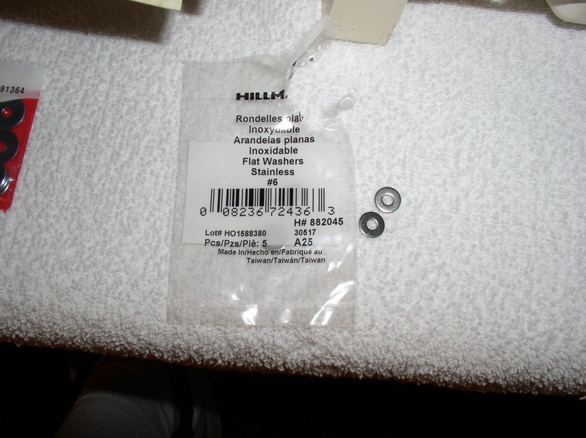
Since I didn't know exactly how much of a gap I needed to address, I purchased
a few different types of small thin washers expecting one would be about right.
These washers seemed to work the best. They are #6 washers from Lowe's and
measure approx. 0.89mm thick. You won't know exactly what size washer will work
until you test fit the washer on the odo tumbler shaft with the tumblers
assembled. We'll do that next.
Place the washer on the end of the odo tumbler shaft (the end where the 100,000
tumbler is) as shown.
Then place the first tumbler on the shaft (the 100,000 value tumbler).
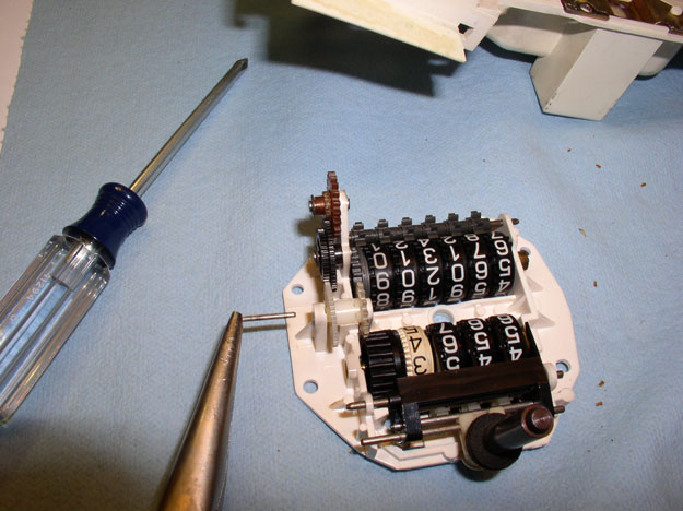
Followed by the next tumbler (10,000 value). You will
notice the string of gears below the tumblers in the picture below. These gears
are positioned between each of the tumblers and are designed to turn the next
higher tumbler when adjacent tumbler transitions from "9" to
"0". It is important that these "transition" gears are
positioned between each of the tumblers as you add tumblers on the shaft.
Add the next tumbler (1,000 value)
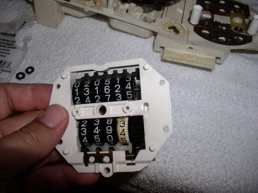
At this point, you can turn the assembly over and begin setting the mileage to
the correct amount (accounting for missing mileage). This is easily done by
simply rotating the third tumbler forward or backward until the highest three
tumblers are set to the right mileage.
Add the next tumbler (100's) ensuring the transition gear is properly
positioned between tumblers and the correct mileage value is visible.
Add the last two tumblers (10's and 1's) ensuring the transition gear is
properly aligned and mileage is correct. At this point, make sure the numbers
on the tumblers align. While I was assembling the tumblers, it was possible to
assemble the tumbler so that it was sort of half-way transitioned to the next
number. To keep the tumblers from spinning while assembling, I used one hand to
hold the tumblers in place (once the numbers were aligned) while I added
tumblers.
After the tumblers are in and aligned, slide the tumbler drive gear between the
last tumbler and the odometer housing as shown. It's at this point you will
discover whether the washer added is too big or not. If you have to force the
drive gear into place, it's probably too tight and you should try a thinner
washer. The goal is to have no slack between the tumblers but at the same time
allow the tumblers to spin freely without force.
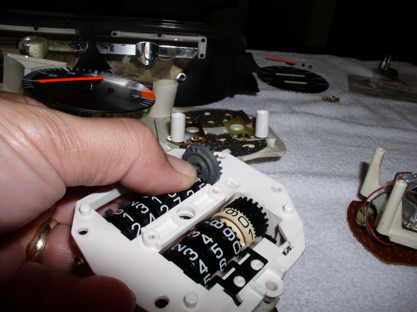
If the driver gear slides into place without significant force, the washer is
about the right size. Double check to ensure the numbers on
the tumblers are aligned as shown.
Next, re-insert the odo tumbler shaft/pin and press it all the way in flush as
shown. You will have to maneuver the far end of the shaft to line up with the
hole in the housing in order to get the shaft in all the way. At this point,
you can test the whole operation by turning the new odometer gear we replaced
earlier. By turning this gear, you should see both the trip meter and odometer
tumblers move. Ensure the gear and tumblers operate smoothly and without force
(i.e., you should not be encountering any significant resistance). I manually
ran it forward about 100 miles and back again.
Now you can reassemble the odo tumbler portion of the unit and the electronic
portion together. Carefully lower the tumbler portion onto the electronic
portion as shown.
Insert the 4 screws and tighten them down. With the screws tightened down, you
can spin the worm gear on the odometer motor and verify everything still moves
as it should (I manually ran it up a couple of miles and back again by moving
the worm gear with my finger). Everything checked out.
Next, replace the speedo face plate oriented as shown.
Insert the 2 securing screws and tighten them down.
Next, grasp the speedo needle by the black plastic center hub and line it up
over the same position on the face plate when it was removed earlier. My needle
was lined up directly over the first tick mark on the face plate. Then, gently
press down evenly on the needle hub but don't use excessive force - the speedo
shaft the that needle hub rests on can easily bend.
Once the needle hub is started on the shaft, I spin the needle to ensure it is
installed level on the speedo shaft. In order to get it to fully seat on the
speed shaft and be straight, I would gently rock and press down on the black
needle hub until I had it just right. Spin the needle over the full range of
motion to check for proper operation.
When finished, it looked just like it did before disassembly.
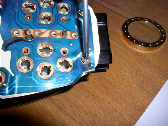
Now you can re-insert the spedo/odo unit back into the instrument housing. Line
up the odometer reset magnetic cylinder so that it falls into it's housing as
pictured below.
Lower the unit into the housing until it is fully seated as shown.
Check for proper operation of the odometer reset mechanism by pressing down on
the lever arm as shown and the trip tumblers should reset to all
"0"s. The reset mechanism should operate smoothly.
Next, if you DID NOT remove the plastic printed circuit board on the back of
the instrument cluster earlier, you only need to replace the plastic instrument
face cover over the instrument gauges as shown....
Then turn over the instrument cluster and secure the face plate to the cluster
housing using the perimeter screws as shown.

And finally, secure the speedo/odo unit to the cluster housing using the 4
small Phillips screws as shown and the instrument cluster is ready to go back
into the pod/car.
However, if you did remove the plastic circuit board, you'll need to reassemble
the cluster as follows: First, place the temperature/fuel gauge and oil
pressure/alternator gauge back into the instrument cluster as pictured.
Then set the plastic cover plate over the instrumentation gauges as shown.
Turn the instrument cluster face down as pictured.
Begin re-attaching the plastic circuit board to the back of the cluster
housing. Start by lining up the speedo hard circuit board pins (4 of them) with
the holes in the back of the cluster housing as shown below. Then press the
hard circuit card down so it is flush with the back of the cluster housing.
Secure the hard circuit card for the speedo to the cluster housing using the 2
small Phillips screws as shown.
Next, begin lining up the small holes in the plastic circuit board with the
guide pins in the back of the cluster housing. Press the plastic material over
the guide pins.
Secure all the plastic material using these guide pins over the back of the
cluster housing.
Install and tighten the tachometer contact nuts using the 7mm nut driver
Then secure the instrument face plate to the cluster
housing using the perimeter screws as shown. In the one corner, don't forget to
include the lapped plastic connector under the screw as pictured below.
Next, finish attaching the speedo unit to the cluster housing using the small
Phillips screws
Then re-attach the odometer reset contact leads using the 2 Phillips screws.
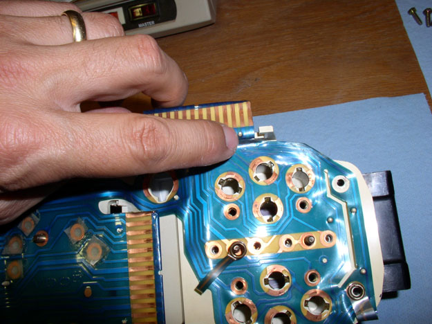
Next, install the gauge pins and 7mm nuts on all four of the gauges as shown.
Remember the oil pressure guage also has a lapped plastic connector to be
located under the 7mm nut (you can see it located next to my thumb in the
picture below).
Tighten down the pins with the 7mm nut driver.
Next, install the 68 ohm resistor over the alternator contact screws and secure
it with the two flat blade screws.
Install the remaining gauge contact screws - 2 flat blade screws per gauge.
Re-install the small warning lights. Insert the light fixture and rotate
clockwise 90 degrees.
Next, install the instrument cluster lighting bulbs (3 of them). Insert the
bulbs and rotate clockwise 90 degrees.
Finally, re-install the harness connector locking covers (3 of them). Ensure
the locking prongs are engaged with the cluster housing as shown.
Now the instrument cluster is ready to be installed in the pod/car.
INSTALLING THE CLUSTER BACK INTO THE
POD
To re-install the instrument cluster back into the pod is
basically the reverse procedure of taking it out. I've included the pics here
for reference. First, lift up the left side of the cluster while inserting the
right side into the pod - there is a molded receiver that fits over the Allen
head bolt guide bushings (see pic below).
Next, ensure the left side allen bolt guide bushings
are installed in the instrument cluster housing receiver....
Then, lower the left side of the cluster into the pod cavity as shown.
Whle holding the cluster in place with one hand, rotate the pod forward.....
....and up over the steering column as shown.
Then, before setting the pod in place, re-attach the rear wiring harness to the
cluster connector. Push the harness into the connector until is locks into
place. Then push the pod back into place against the dash.
Next, connect the two lower harness connectors (left and right) underneath the
pod as pictured.
Then install the signal/wiper/cruise cluster by slipping it on over the
steering column and pushing it far enough down the column that you can connect
the two keyed harness connectors.
Lifting up the pod slightly, continue pushing/walking the signal/wiper/cruise
cluster down the steering column until it clears the portion of the pod that
fits over the cluster.
Then, lower the pod and line up the ignition switch hole with the ignition switch
and push the pod back over the ignition switch.
Next, install the ignition switch grommet.
Recall that the long Allen bolt secures the left side of the pod and the
shorter bolt secures the right.
Install the left side Allen bolt as shown. You may have to slightly maneuver
the pod to line up the bolt guide bushings with the metal flange on the dash
framing.
Next, install the right side Allen bolt in the same manner.
Next, you will need to locate the final resting position of the
signal/wiper/cruise cluster so that the horn contact does not have too much
pressure but also makes light contact. Place the steering wheel back onto the
steering column and seat it all the way down. Then inspect the horn contact on
the wheel making contact with the spring contact on the cluster. The steering
wheel horn contact should just barely make contact with the spring contact on
the cluster. You can watch for it as you slide the wheel on to the steering
column. Move the signal/wiper/cruise cluster up or down the column to get the
right contact. Too heavy of a contact will result in a scraping sound when
turning the steering wheel and no contact will result in the horn not working.
After you've finally positioned the cluster, remove the steering wheel. If your
signal/wiper/cruise cluster had a clamping bolt on it, now's the time to
tighten the bolt down to secure the cluster to the steering column. Mine did have
the clamp but no bolt. Then attach the lower cluster cover as shown.
Secure the cover with the Phillips screw.....
...and the two 10mm bolts.
Next, position the lower plastic pod cover plate by inserting the prongs first
then sliding the cover forward to lock it into place.
Then secure the cover plate with the two Phillips screws - one at each end.
Raise the tilt wheel paddle and lock it in place.
Next, you'll attach the steering wheel. According to Technical Bulletin #9205
titled “Noise When Turning Steering Wheel”, do not apply any lubricant to the
horn contact ring or the spring contact strip on the cruise/signal/wiper
cluster. Position the steering wheel in the same orientation as you removed it.
In this case, perfectly straight.
Place the washer and nut on the steering column threads and tighten the nut
with the 27mm socket and ratchet using the 6" extension. Tighten to 36
Ftlbs.
Attach the horn electrical lead to the back of the horn pad as shown.
Position the horn pad so the horn pad contacts with springs ling up with the
contact tabs on the steering wheel. Then press the horn pad into place until
you hear/feel the tabs lock. There are three tabs so you'll want to make sure
all three are locked and the pad is level with the steering wheel.
Finally, you will reconnect the negative battery cable using the 13mm combo wrench.
After connecting the battery, test the horn for proper operation.
Next, you can start the car and take it for a test spin and try out the newly
repaired odometer! If everything checks out, you're done! CONGR
Please feel free to comment and recommend improvements to this post as I (and
the community) welcome shortcuts and improvements on this procedure. THANKS for
reading!