1987 Timing Belt and Water Pump
Procedure w/pics
Between the timing belt and water pump repair I did on Virginia
last winter and the Water Pump block repair procedure I did on Virginia a
couple of months ago, I had enough pics to document
the TB and WP procedure so thought I'd share the process I followed. I'm not an
expert mechanic by any means but wanted to show the step by step process as a
pictorial guide for other newbies such as myself that
may want to try this maintenance procedure themselves.
There's quite a few pics in
this write-up (appox. 400) and it's "Newbie Rated" (i.e., a lot of detail). Therefore, I
thought I'd try something new to make it easier to find material in the write-up
more directly. I've broken the entire process into Chapters and will precede
each post that starts a new Chapter with a heading that you can find easily
with the search function. For example, if you want to see the section on
Removing and Repairing Timing Belt Tensioner, search for "CH14". A
table of contents has been added that includes the Chapter number and title for
reference. Special tools and Parts section is also included.
This procedure is for a 1987 (early) S4 928 (vin 0349) - our "
Table of Contents:
CH01 Parts, Tools, and Preparation
CH02 Draining Coolant and Removing Coolant Hoses
CH03 Removing Accessory Belts
CH04 Removing Fan Shroud
CH05 Removing Power Steering Pump and Alternator
CH06 Removing Upper Cam Gear Covers, Setting Crank at 45 Degrees BTDC
CH07 Removing Accessory Belt Pulleys and Center Timing Belt Cover
CH08 Removing Tensioner Pulley and Timing Belt
CH09 Removing Water Pump
CH10 Removing Oil Pump Gear and Rear Timing Belt Cover
CH11 Removing Oil Pump and Replacing O-Rings
CH12 Installing Rear Timing Belt Cover and Oil Pump Gear
CH13 Repairing/Replacing Tensioner Pulley and Tensioner Bushings
CH14 Removing and Repairing Timing Belt Tensioner
CH15 Installing Water Pump
CH16 Installing Timing Belt Tensioner
CH17 Installing Timing Belt Tensioner Pulley
CH18 Installing Timing Belt and Setting Tension
CH19 Installing Center Timing Belt Cover and Routing Engine Harness
CH20 Filling Tensioner with Gear Oil
CH21 Installing Power Steering Pump and Alternator
CH22 Installing Upper Cam Gear Covers
CH23 Installing Fan Shroud
CH24 Installing Accessory Belts and Pulleys
CH25 Installing Distributor Caps, Dipstick, Spark Plug Wires
CH26 Installing Coolant Hoses
CH27 Wrap Up
Here we go.....
CH01 Parts, Tools, and
Preparation
For this procedure, I replaced the following parts. You do not
have to replace all the parts I did for this procedure and you may find you
want to replace a few optional parts that I did not replace in this procedure.
After you have "dug into" the job, you may want to assess your
specific situation on what to replace. However, if you know you will be
replacing certain parts, it's recommended that you order the parts you will be replacing
ahead of time so they are available and ready when you start work.
Parts:
Timing Belt
Water Pump
Water Pump Gasket
Tensioner Boot and Clamp
Tensioner-to-Block Gasket
Tensioner Piston O-Ring
Tensioner Pulley
Tensioner Bushings
Oil Pump O-Ring
Oil Pump Bolt O-Rings (3)
Anti-Freeze/Coolant and Distilled Water
90w Gear Oil
Optional Parts (instructions not included in this procedure)
Tensioner Idler Pulley
Front Crank Shaft Seal
Front Oil Pump Seal
Most of the Special Tools I used include:
Timing Belt Tensioner Tool (Kempf Tool)
Flywheel Lock Tool
2-Jaw, 3-Jaw, Power Steering Pulley Pullers
Breaker Bar and Torque Wrench capable of 295 Nm (217 Ftlbs)
Medium sized prybar and gasket scraper
Preparation:
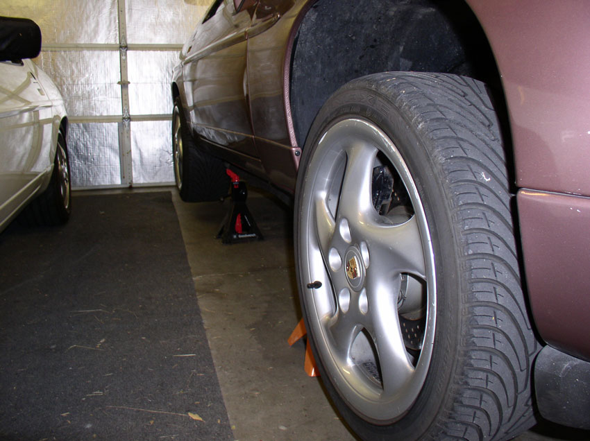
I used Porken's lift bars to lift and support the car. Harbor Freight has some
excellent heavy duty jack stands that work well for this application. Lift and
support the car so there is plenty of room underneath to work.
Next, install service covers (if you have them) or other suitable covers for
your fenders and front bumper.
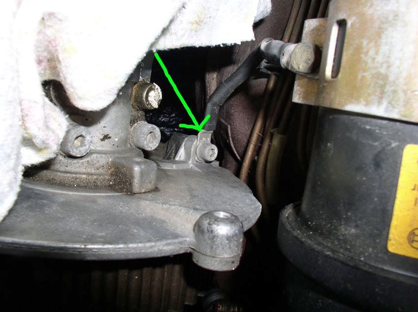
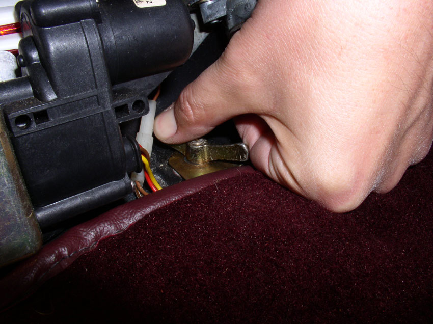
Then, disconnect the negative cable on the battery. I usually remove the spare
tire and remove the cable from the battery post. However, this time I decided
to "live on the edge" and disconnect the negative battery cable from
the grounding point behind the tool cover as you can see from the pic below.
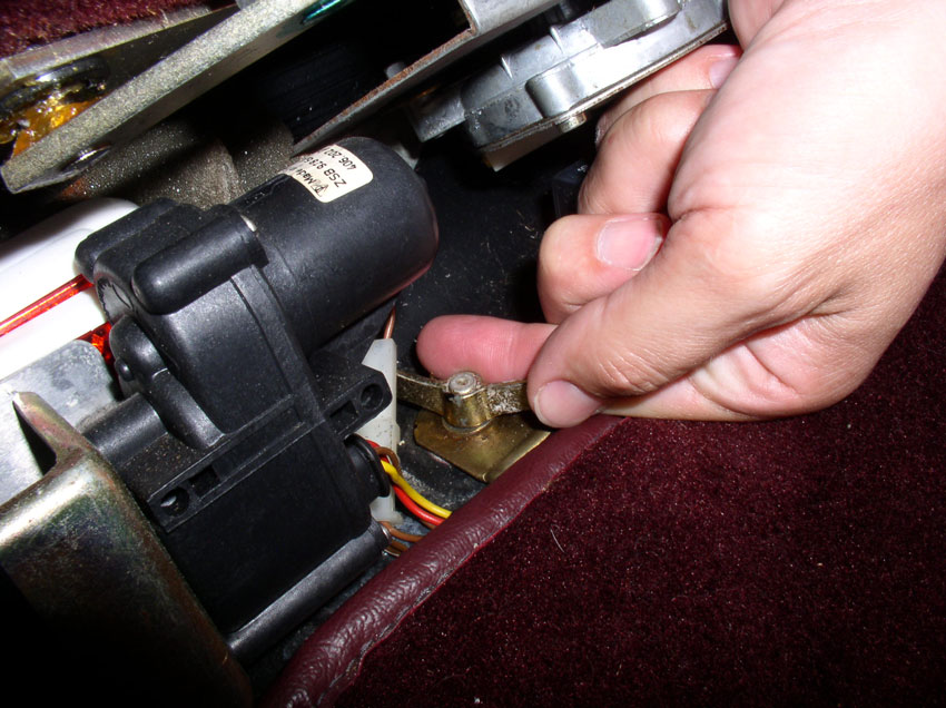
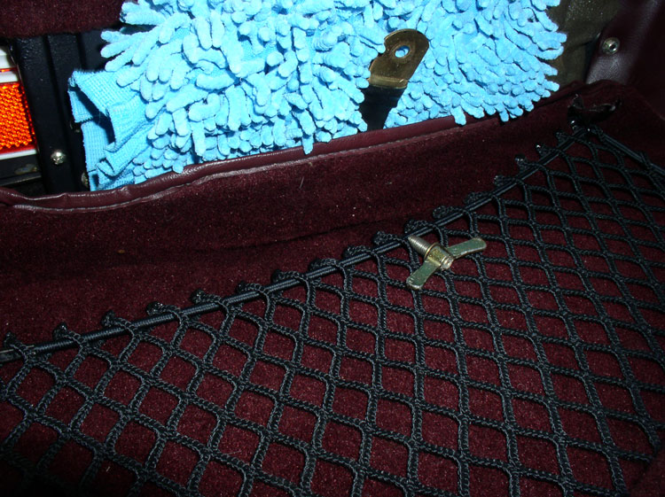
Once the cable is detached, I placed a thick barrier between it and any
possible grounding points. All in all, I think I prefer to go the extra steps
and disconnect the cable from the battery. But you never know what you like
best until you try something different!
Next remove both belly pans. From the factory, the rear pan is aluminum while
the front pan is a plastic composite. Remove the rear pan first.
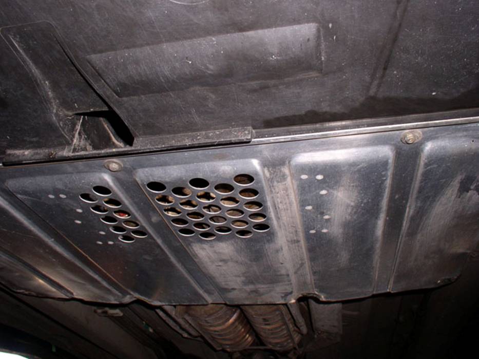
The rear pan is held on by nine (9) 8mm screws. Three across
the front, four across the back and one on each side. When the screws
are removed, you will need to slide the pan rearward to clear the front belly
pan.
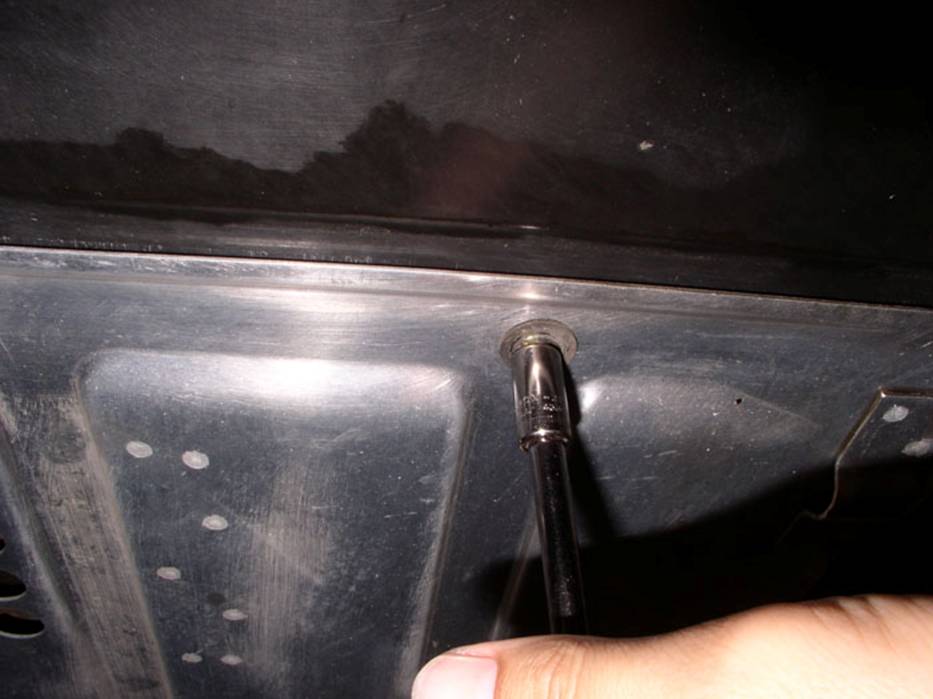
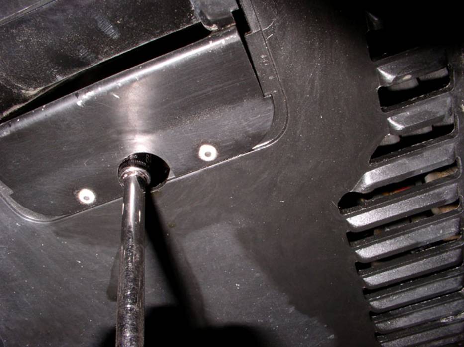
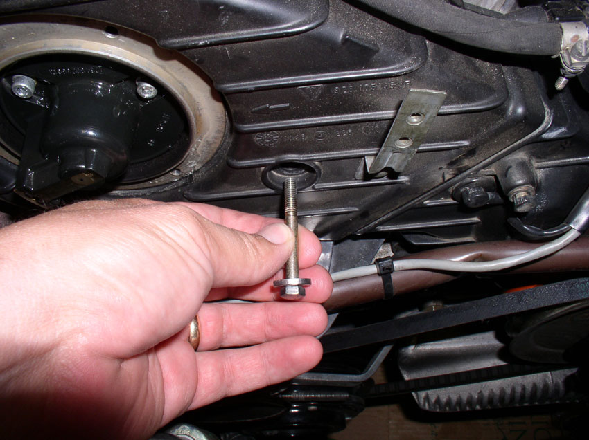
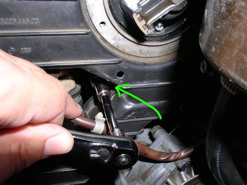
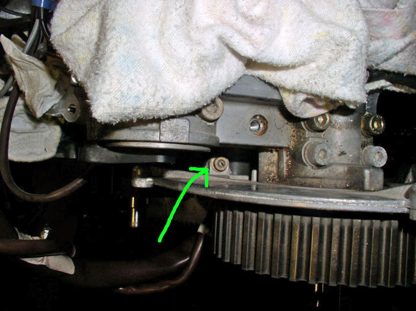
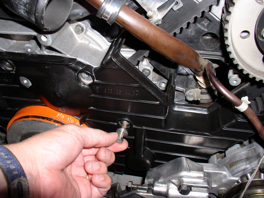
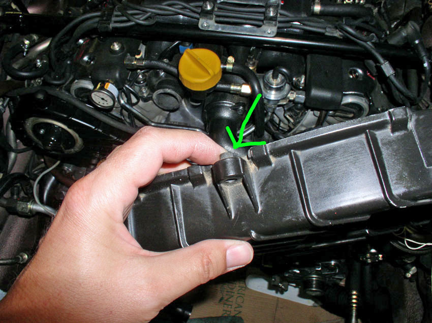
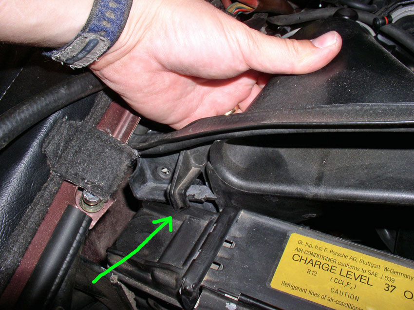
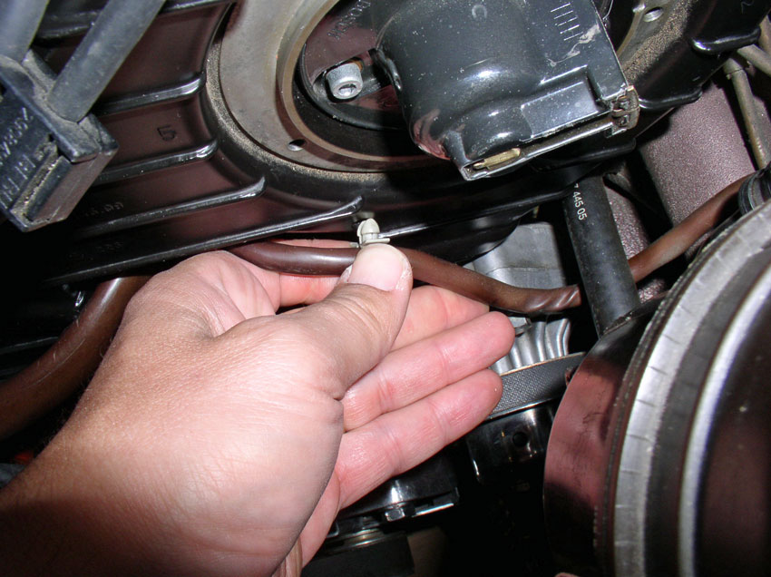
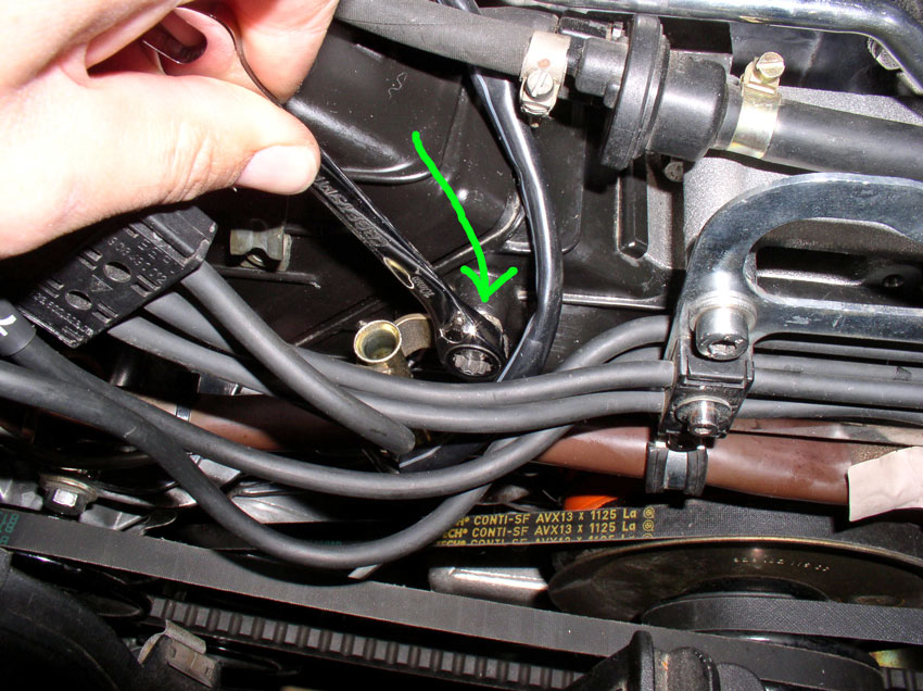
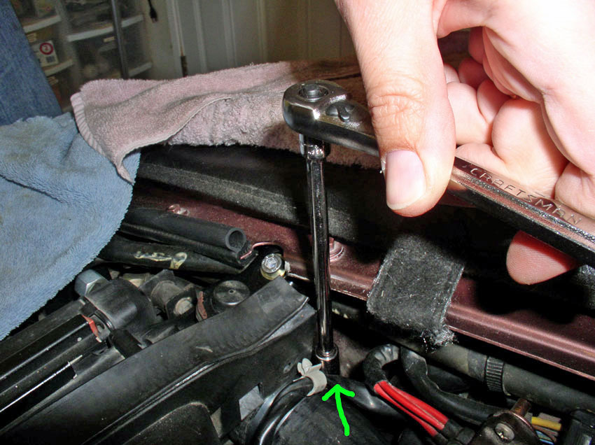
The front pan also has nine (9) 8mm screws AND two (2) 10mm bolts. Five across
the front of the pan, one on each side of the pan and two 8mm screws counter
sunk in these holes pictured below. Remove the 9 8mm screws first...
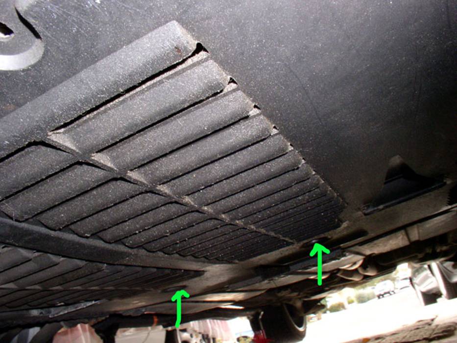
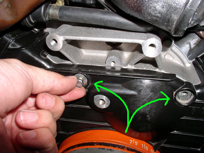
...then remove the two remaining 10mm bolts (see arrows in pic
below) while holding the belly pan up with one hand. Lower the belly pan and
place both out of the way.
CH02 Draining Coolant and
Removing Coolant Hoses
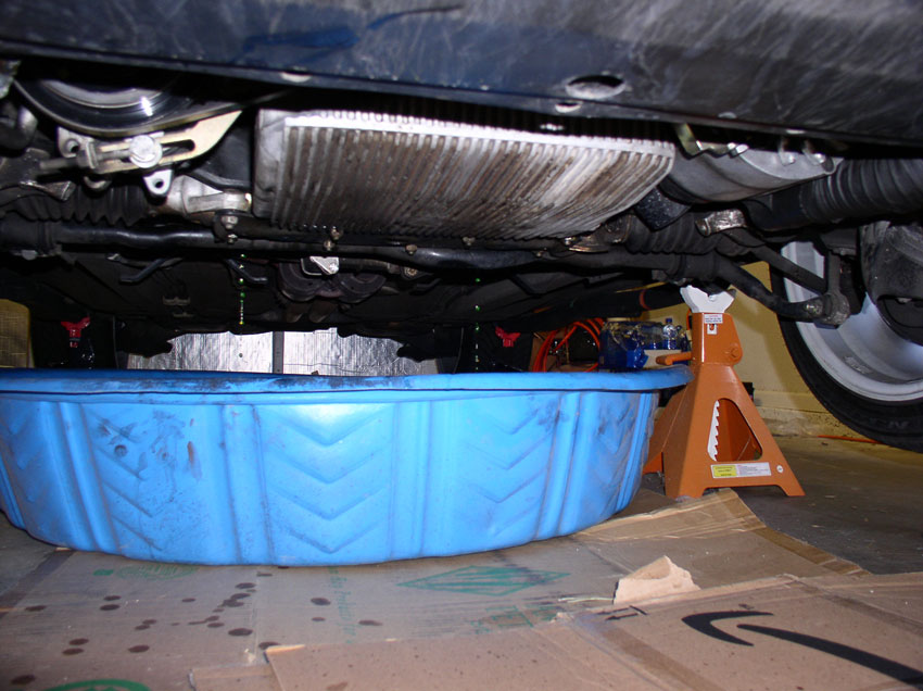
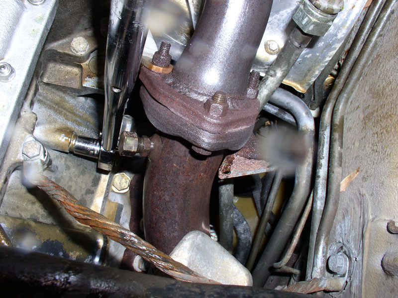
First, I drained the block of coolant. Get a suitable container
ready for catching the coolant. I used a small kiddy wading pool. The drain
plugs are located one on each side of the block about 3/4 toward the rear of
the block. The drain plugs are 13mm bolts. I use a 13mm socket and long handle
socket wrench.
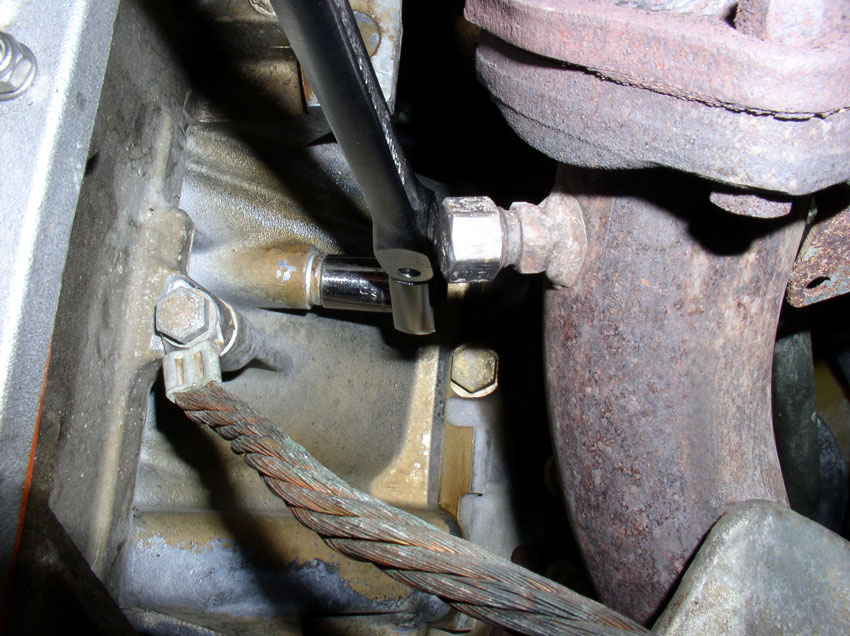
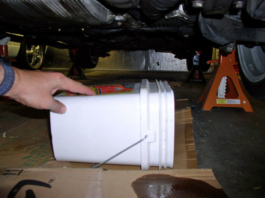
Once you take out the bolt, coolant will begin to slowly drain. Go ahead and
position the kiddy pool in place under the one bolt you just took out and begin
taking out the other bolt on the opposite side of the block. With both bolts
out, position the kiddy pool under both drain plugs to catch the coolant as
shown below.
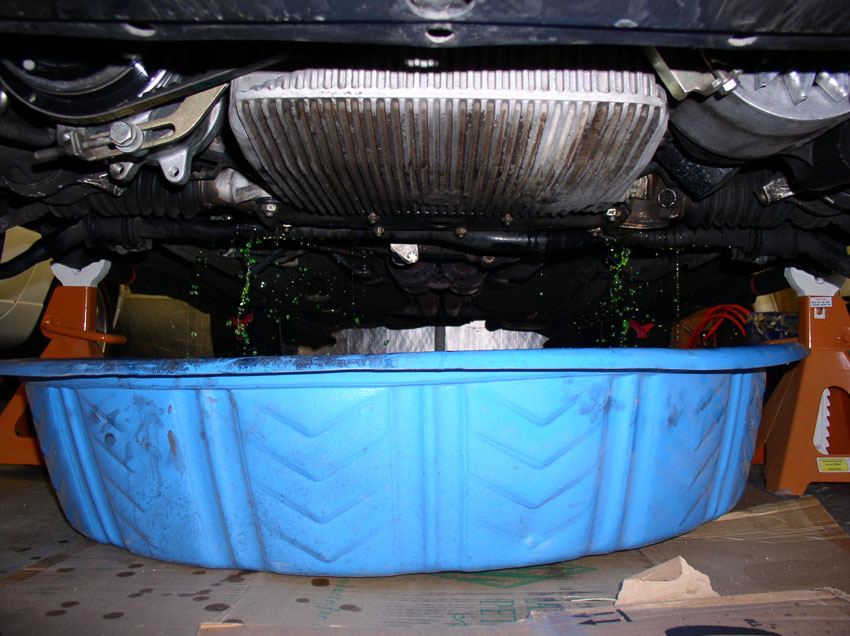
Then go topside, and open the coolant reservoir cap.....
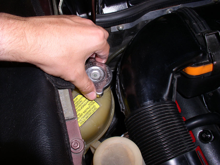
....and the coolant will come out much faster now as seen below.
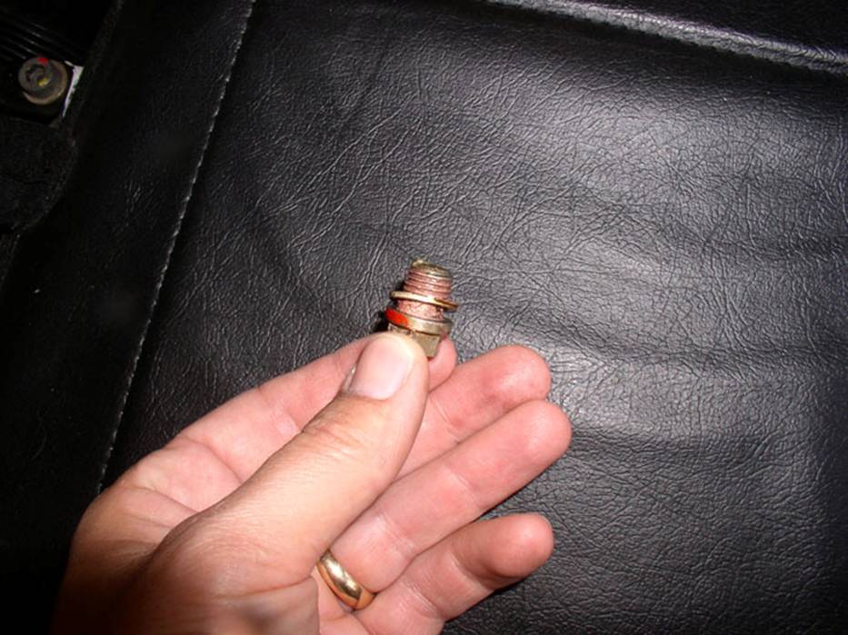
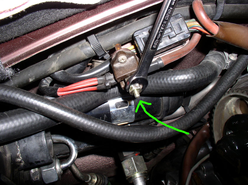
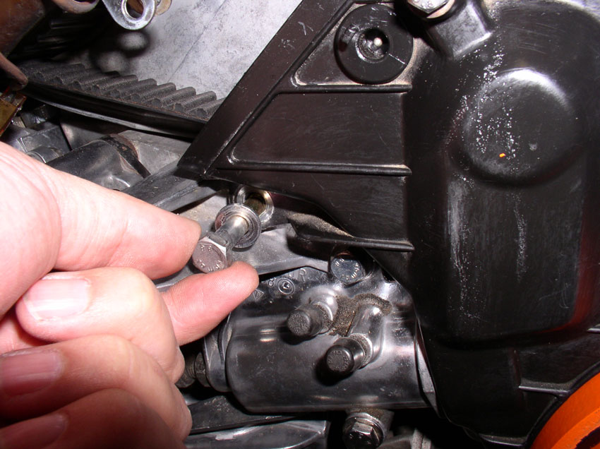
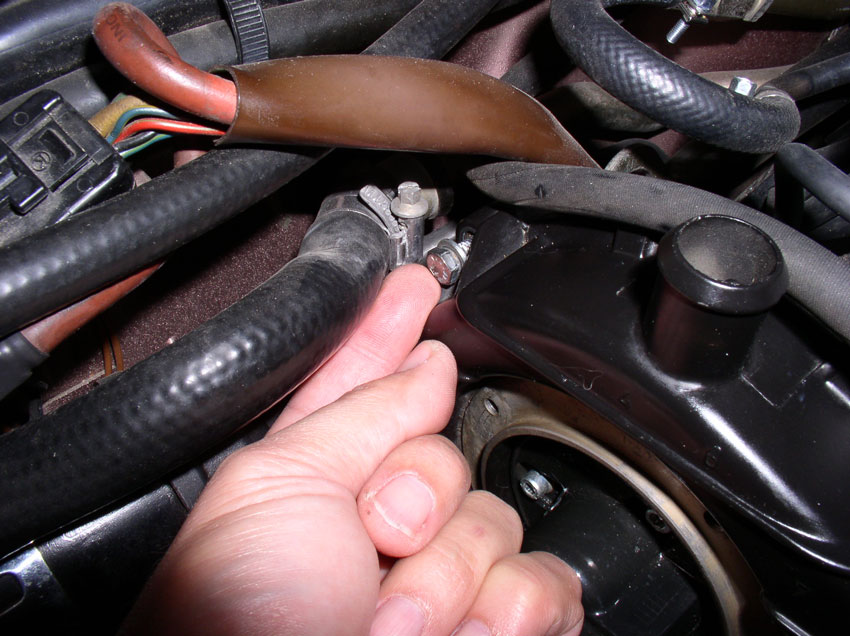
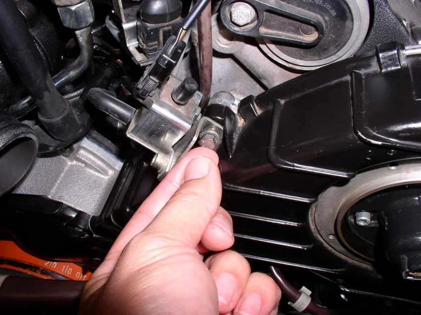
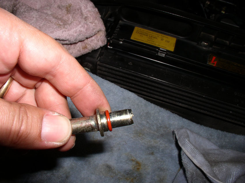
The coolant bolt is an M12 thread and is coated with copper anti-seize. It also
has a sealing ring as can be seen in the pic below.
The sealing ring is size 12mm (ID) X 17mm (OD) and is part number
900.123.055.30. The sealing ring should be inspected and replaced when showing
signs of wear. I usually replace mine every 3rd time I take the bolt out and
re-tighten.
After the coolant has drained from the block, re-install the drain plugs and
torque to 35Nm (25.8 Ftlbs).
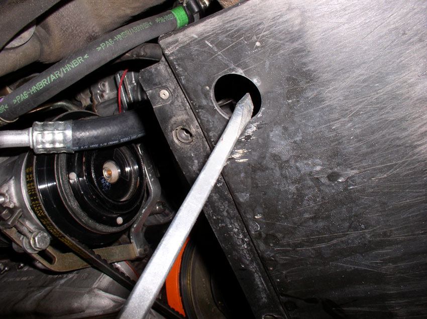
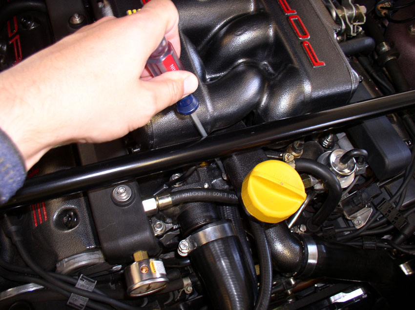
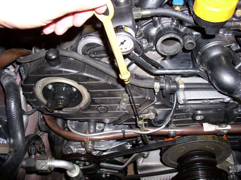
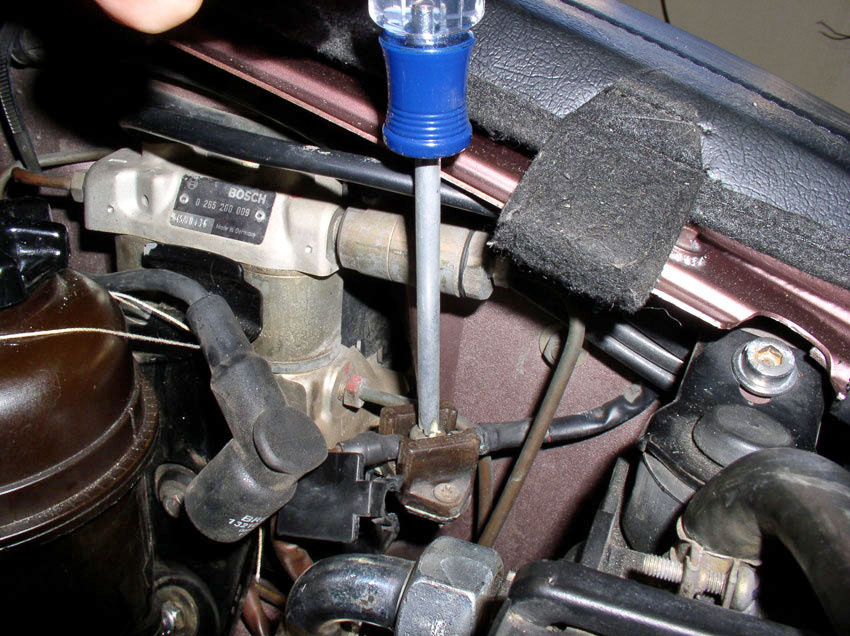
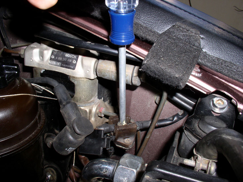
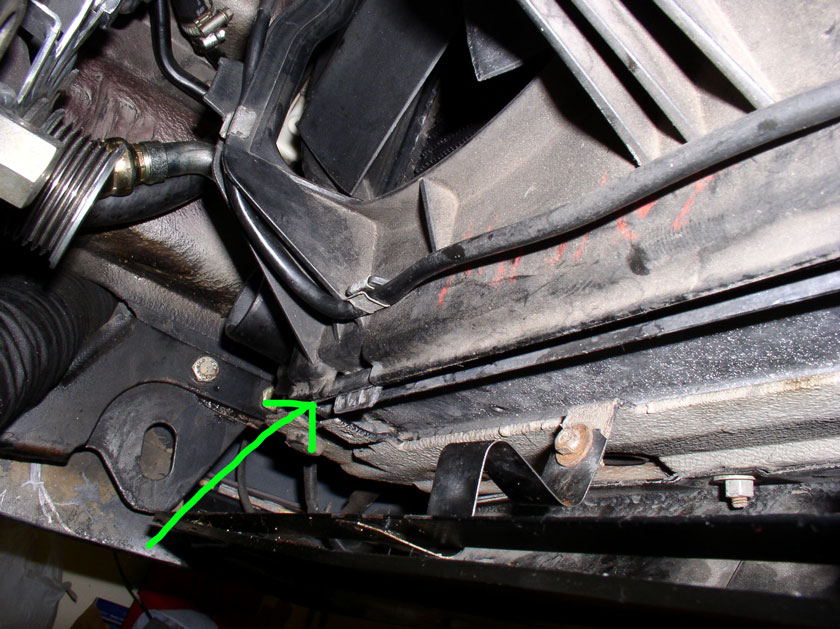
Next, drain the radiator of coolant. The blue drain plug is accessed through
the spoiler access hole as pictured below.
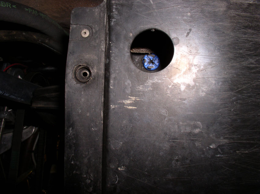
I used a large flat blade screwdriver to take out the screw. Have your kiddy
pool or catch can in place while you are taking out the plug. Inspect the plug
when removed. Like the sealing rings on the block drain plugs, these plugs have
a small o-ring for sealing the radiator drain. Over time they can begin to
leak. If you are noticing leaking at the drain port or notice the o-ring is
worn or damaged, you can order a new drain plug with o-ring from one of the 928
parts vendors (part number 928.106.444.01). After the radiator is finished
draining, replace the drain plug - tightening torque for the blue plastic
radiator plug is only 1.5Nm or 1.1 Ftlbs (about 13 inchpounds) (THANKS, John Speake).
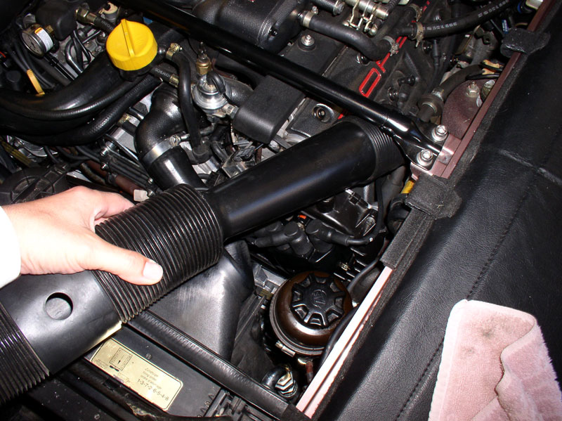
Next, we'll remove the radiator coolant hoses. First, remove the air intake
tubes.
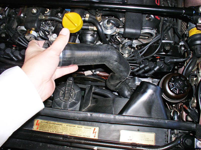
Then, loosen the upper radiator hose clamp at the engine. You can use a flat
blade screwdriver or a 10mm socket wrench. Pull the hose off the thermostat
housing.
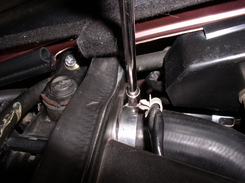
Using a flat blade screwdriver, loosen the clamp on the air bleeder hose also
connected to the thermostat housing. You may need a long screwdriver to reach
the clamp.
Pull the bleeder hose from the thermostat housing as shown. You can either
remove and bag the clamps or tighten them down on the hose after removal so
they don't get lost.
Next, remove the fan wiring harness from its connection point on the fan shroud
as shown.
Then loosen the clamp on the upper hose at the radiator as shown. Again, I
simply used the 10mm socket wrench.
Remove the upper radiator hose and set aside.
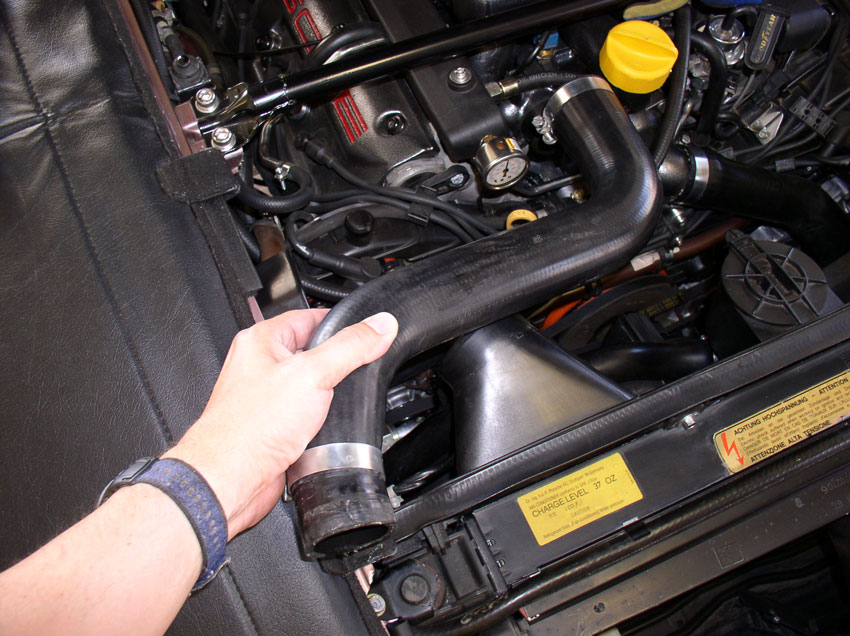
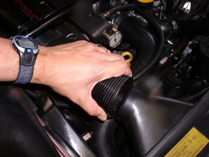
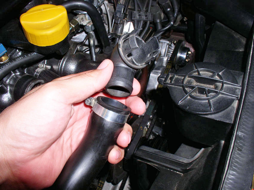
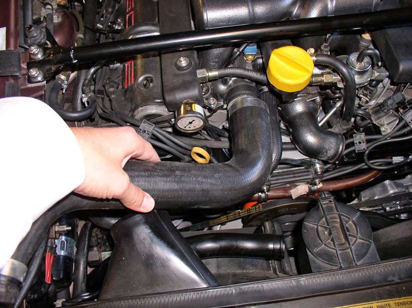
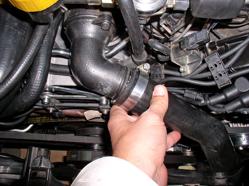
Next, remove the lower radiator hose. Loosen the clamp at the thermostat
housing and remove the hose from the elbow pipe.
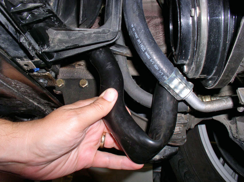
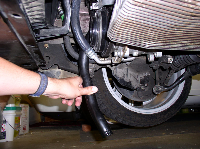
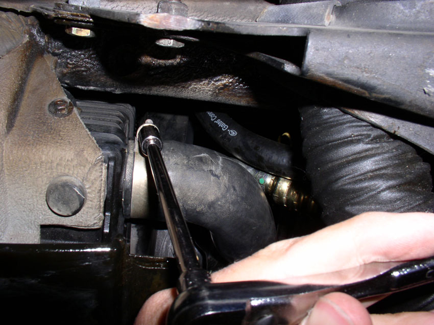
Then, from underneath, loosen the clamp at the radiator (assuming your clamp is
facing downward. If not, you may have to access it from above.
Have your catch can ready in case there is residual coolant in the hose when
you take it off. Remove the lower radiator hose and set it aside.
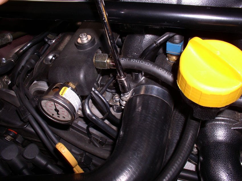
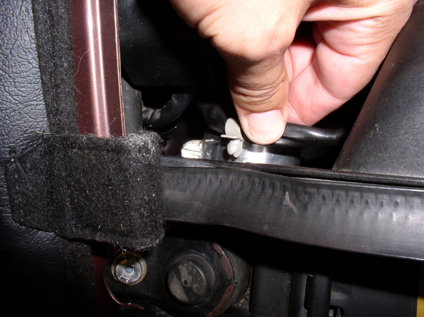
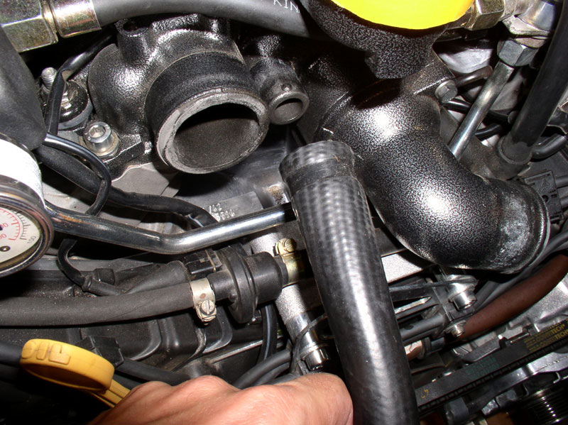
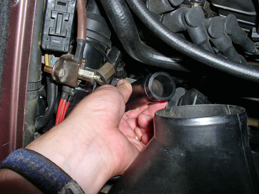
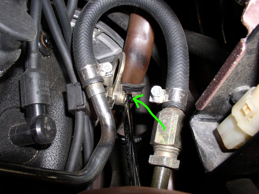
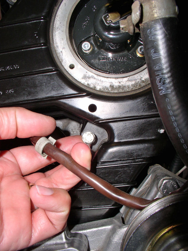
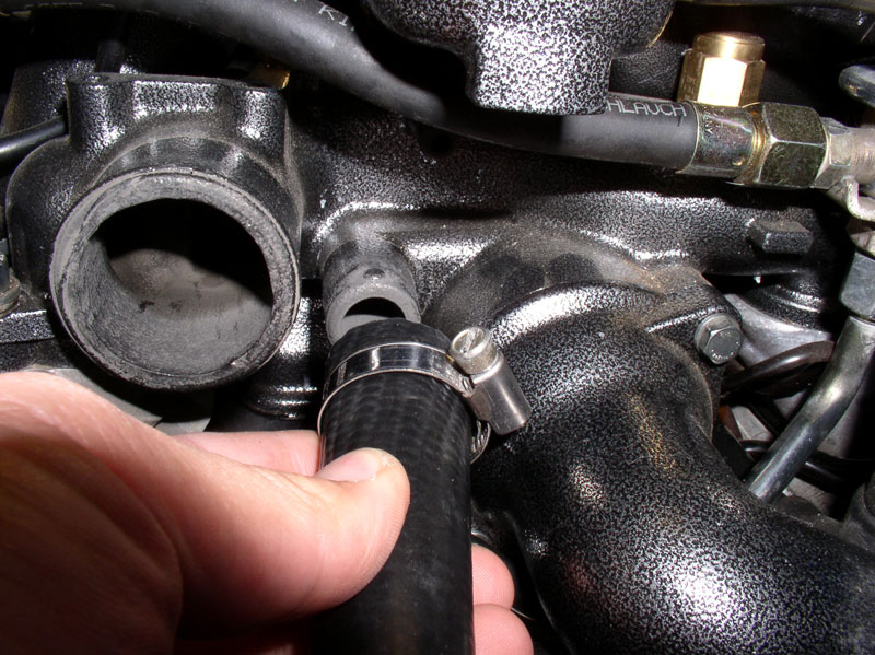
Lastly, remove the heater return hose from the thermostat housing.
I used a long flat blade screwdriver to loosen the clamp as shown.
Pull the hose from the thermostat housing. There is almost always coolant left
in this hose so have your catch can ready when you pull it off. Then point it
downward (between the fan and engine) so the coolant can drain out into your
catch can. Then set the hose out of the way. There is no need to disconnect the
hose at the other end.
CH03 Removing Accessory Belts
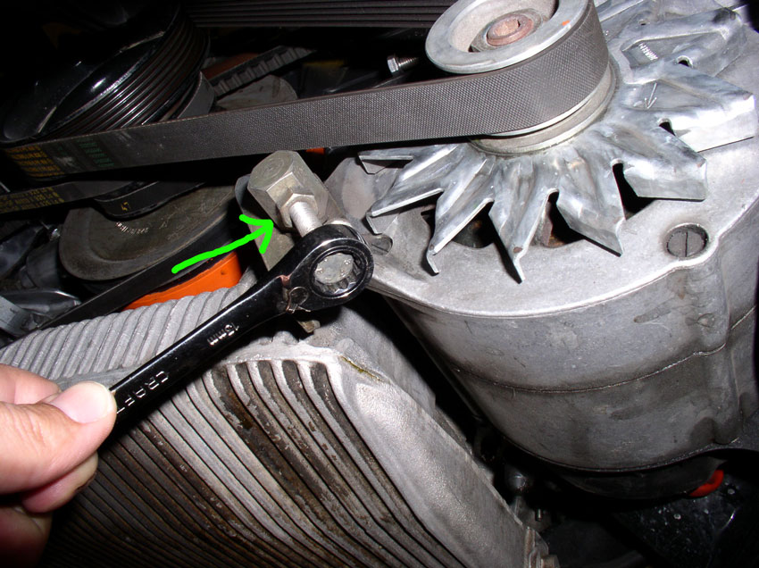
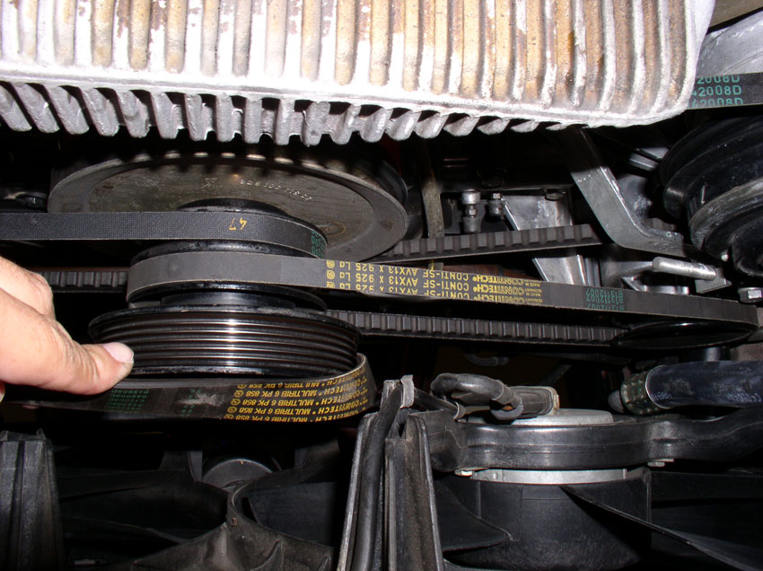
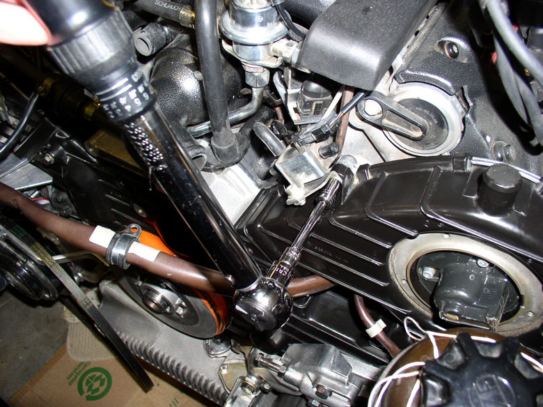
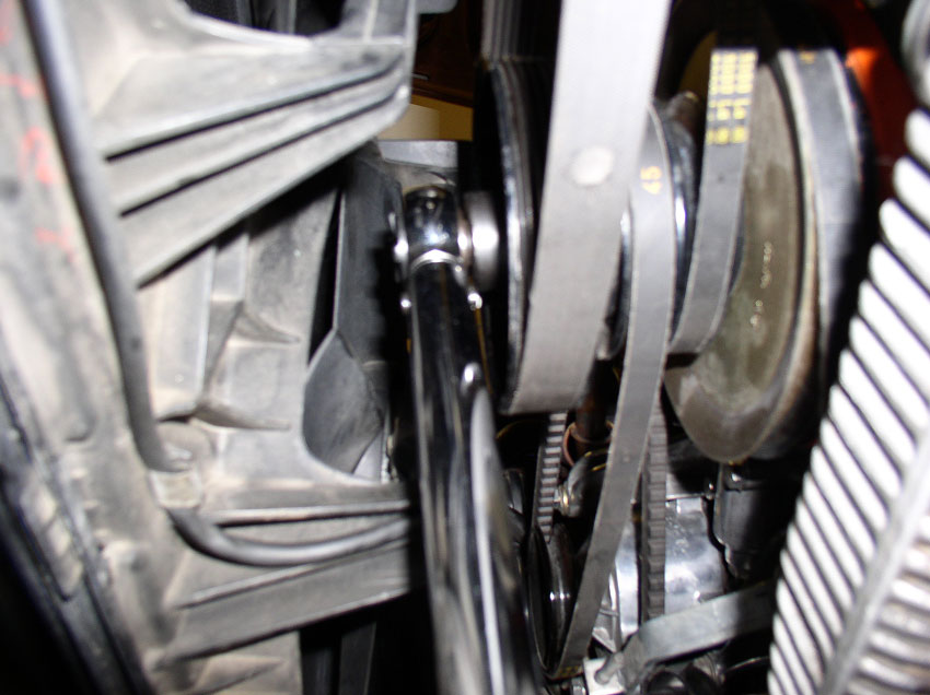
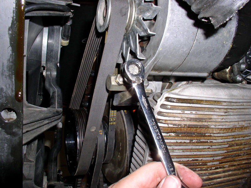
To remove the accessory belts, start with the outermost belt
(alternator) and work toward the innermost belt (A/C). First, loosen the
alternator pivot bolt as shown below. It's a 13mm bolt with M10 threads and
130mm in length. Do not remove the bolt yet.
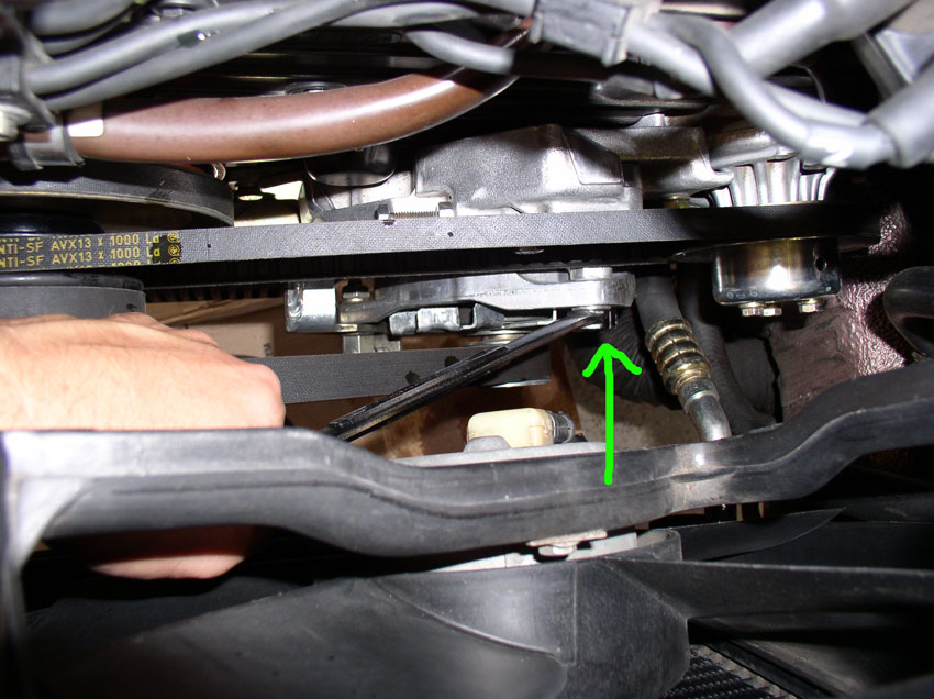
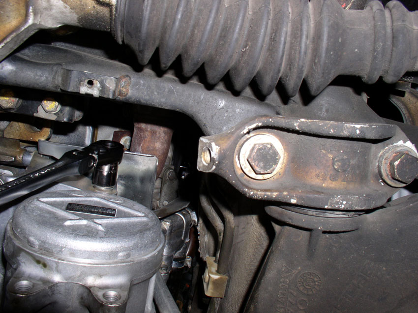
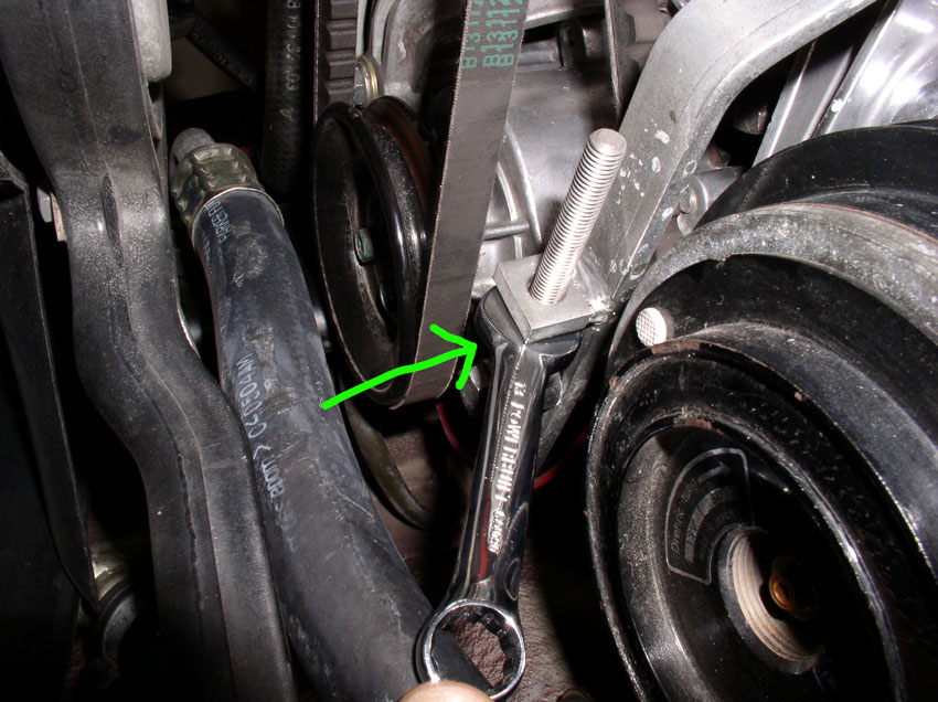
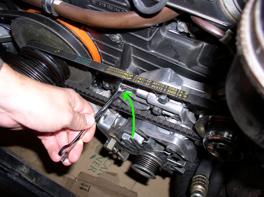
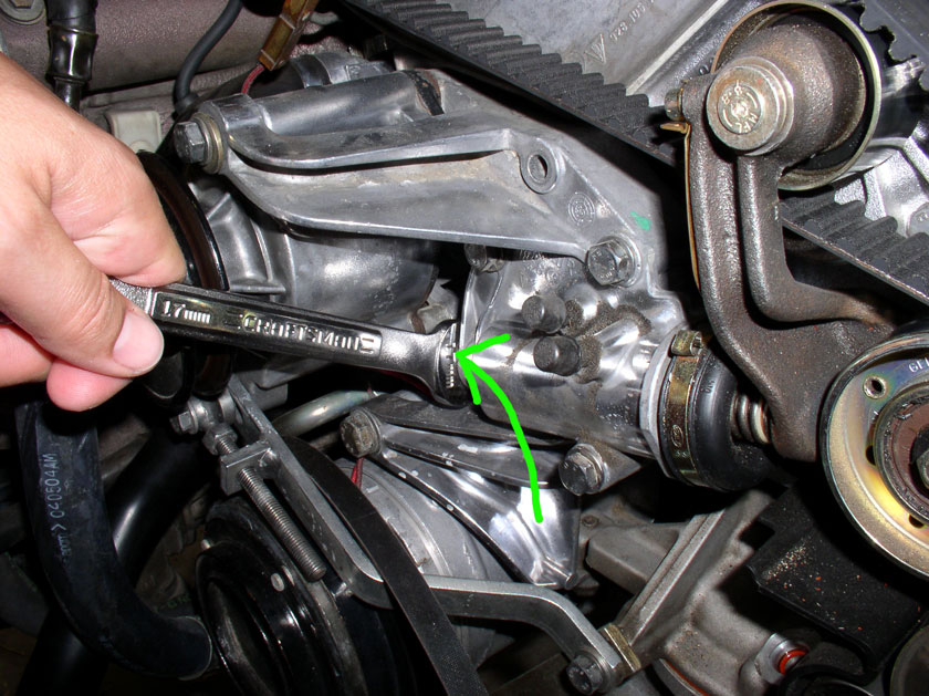
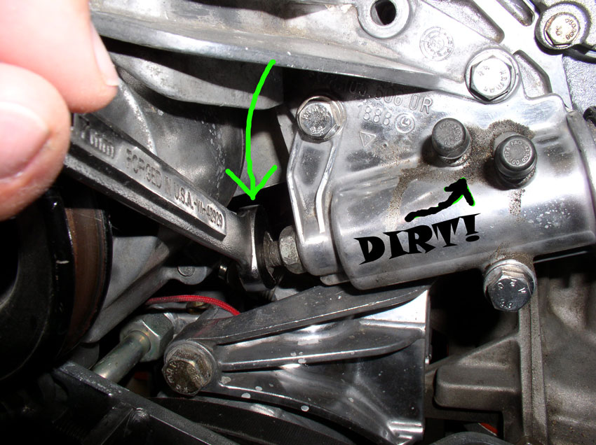
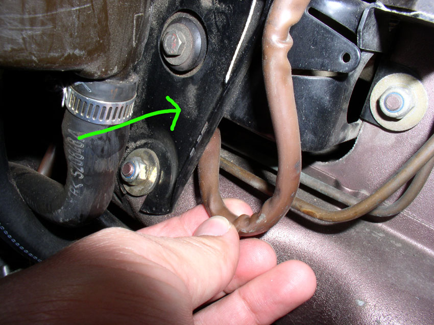
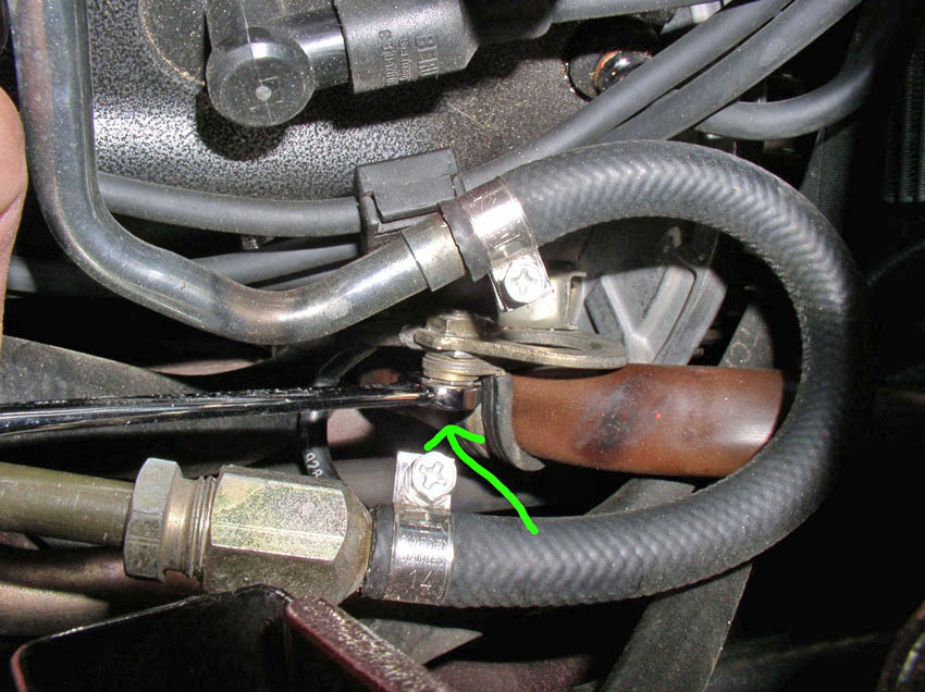
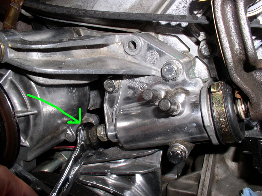
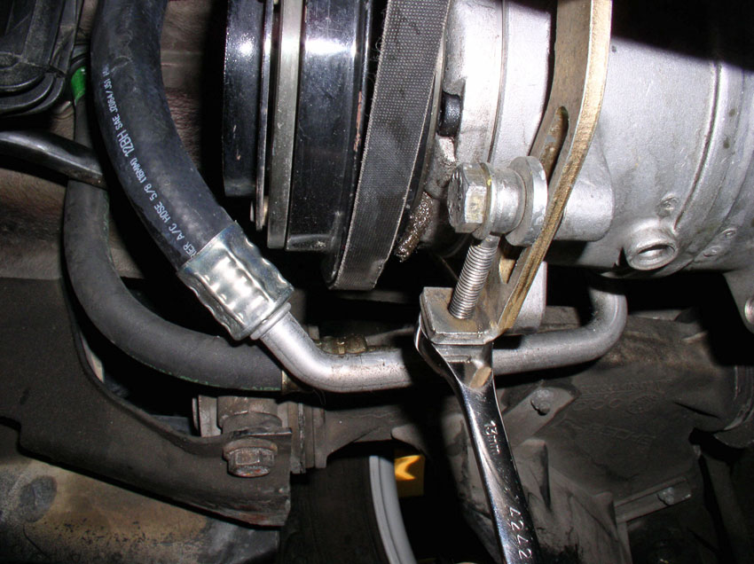
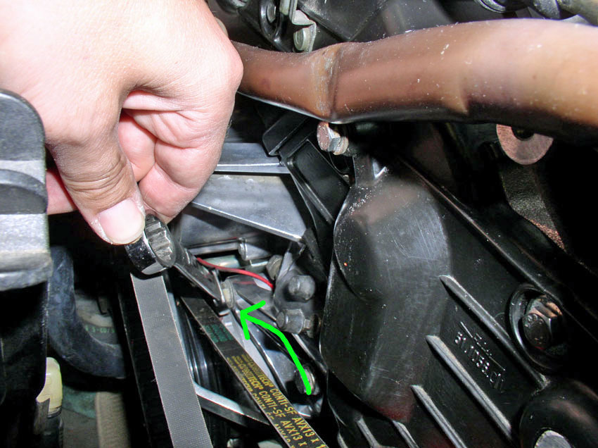
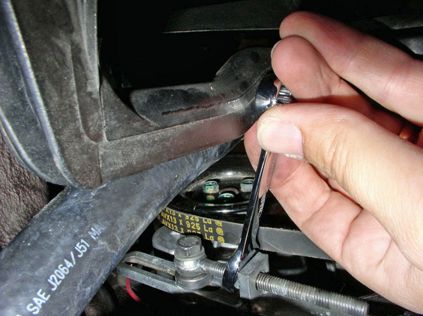
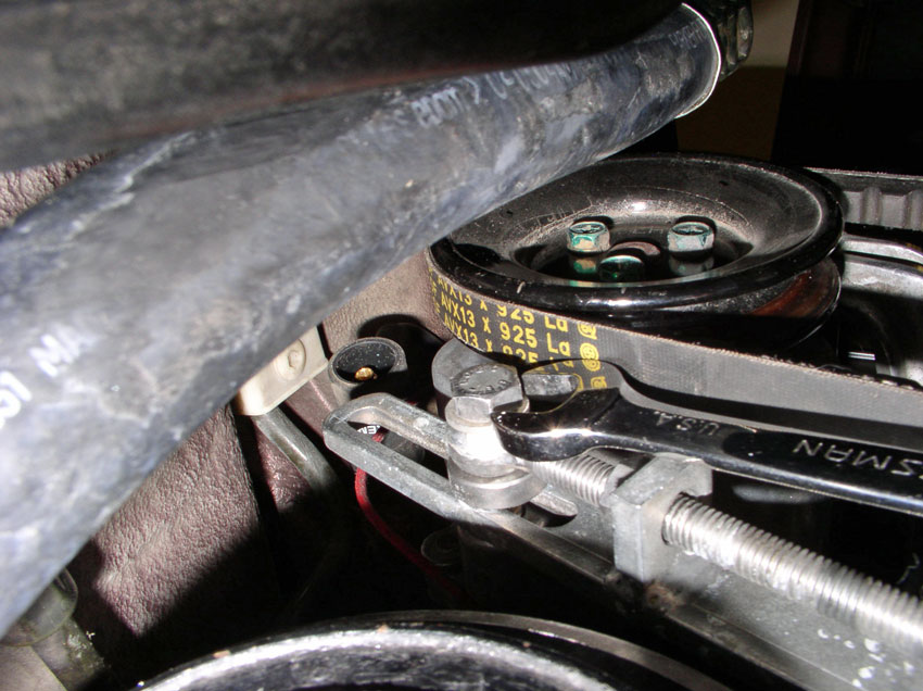
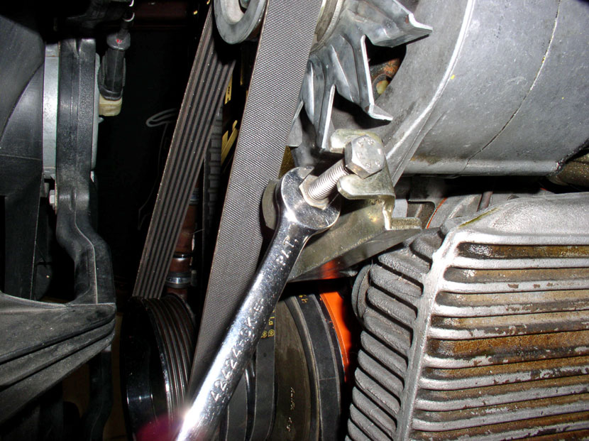
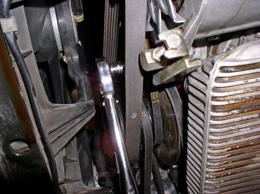
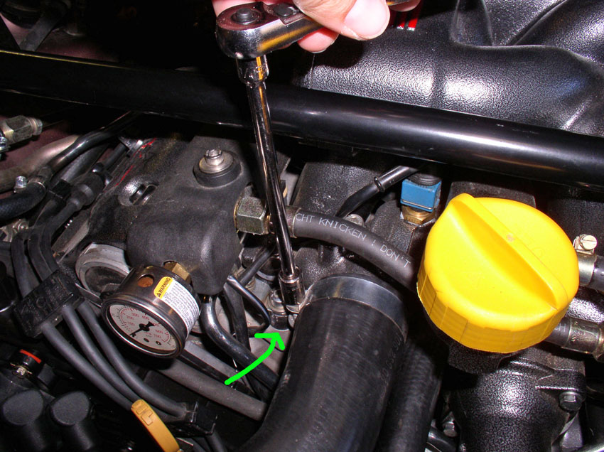
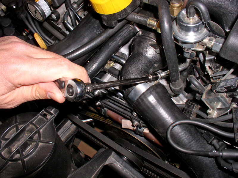
Next, from underneath, loosen the adjustment bolt locking nut (as indicated by
the arrow), then begin loosening the adjuster bolt. Both take a 13mm wrench.
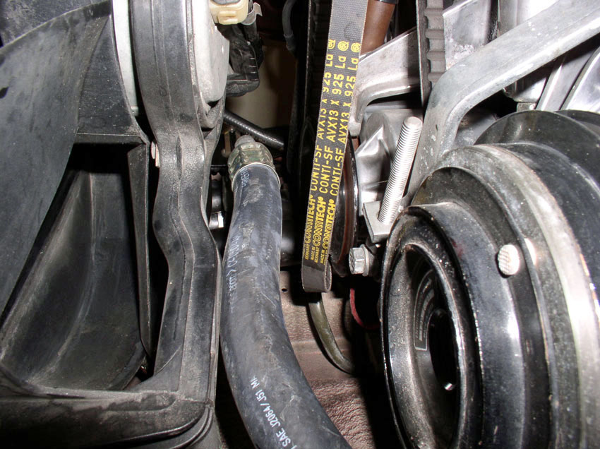
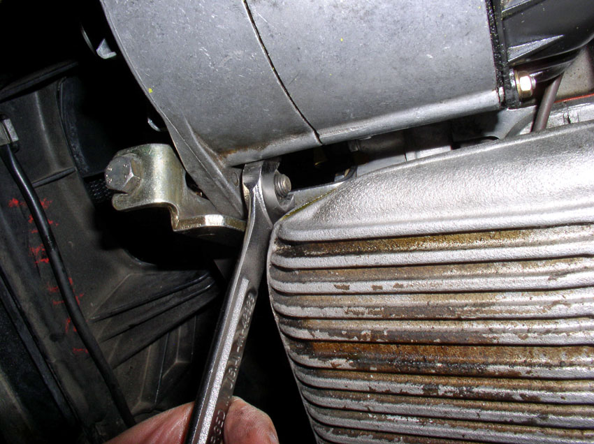
Continue to loosen the adjuster nut until you have slack in the belt as shown.
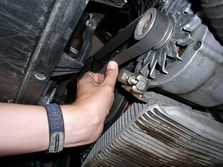
When you have enough slack in the belt, remove it from the pulleys.
Next, remove the air pump belt. However, before I could remove the air pump
belt, I needed to loosen the A/C compressor so I could move it out of the way
then I could adjust the air pump enough to remove the belt. To loosen the A/C
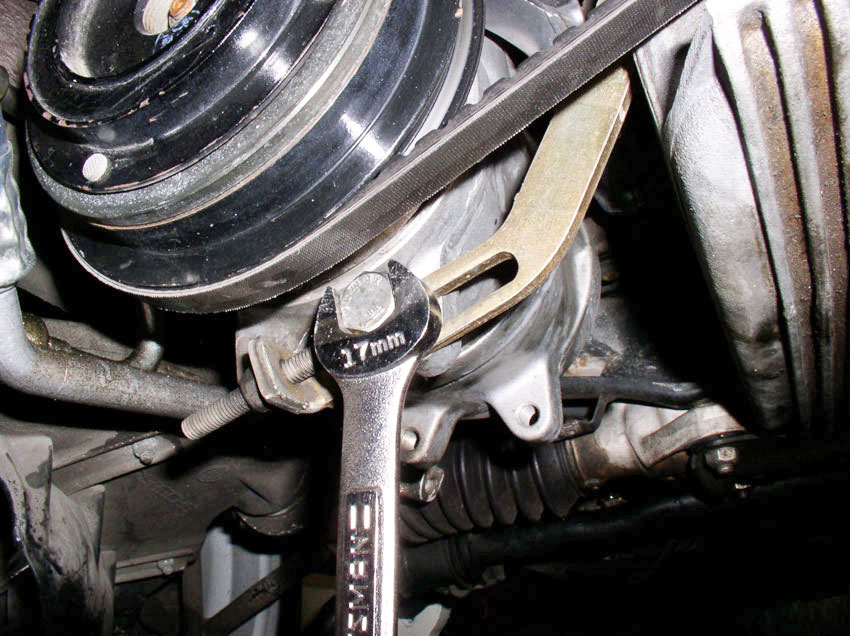
compressor, start by loosening the rear pivot bolt. The rear bolt is an M10
thread and 45mm in length. The bolt head, IIRC was 17mm.
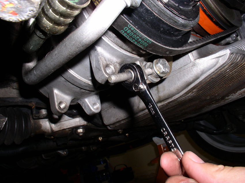
Then, loosen the front pivot bolt. This bolt is also M10 and 33mm long. It
takes a 17mm wrench to loosen.
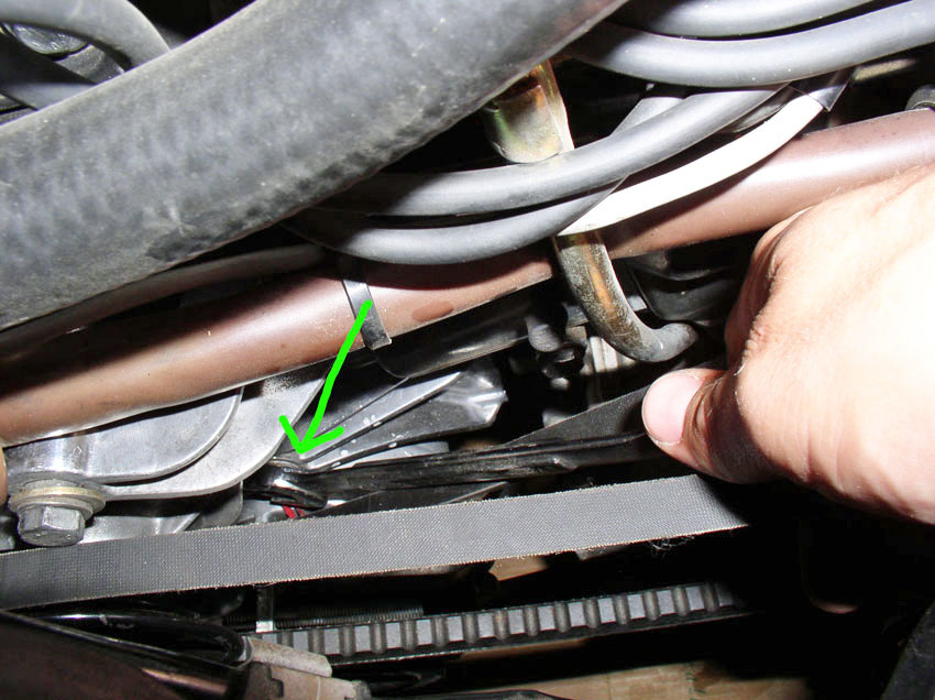
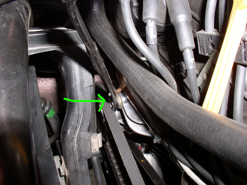
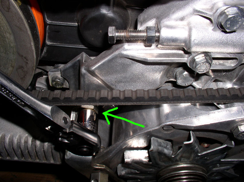
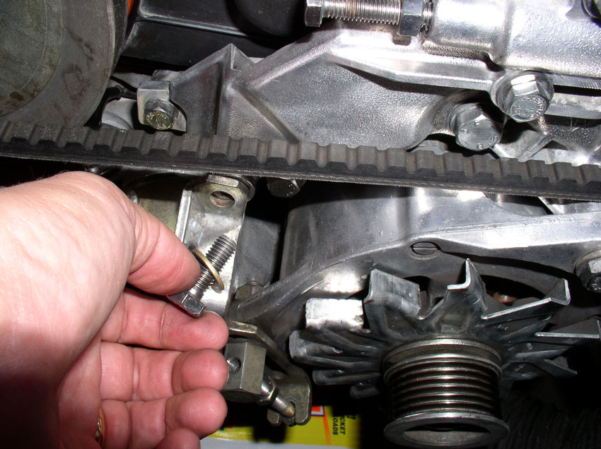
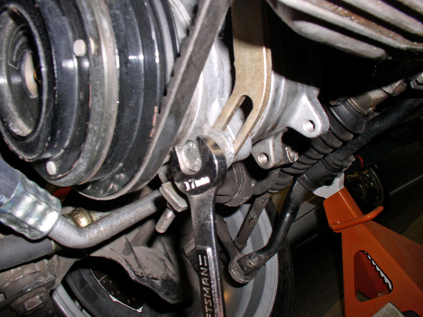
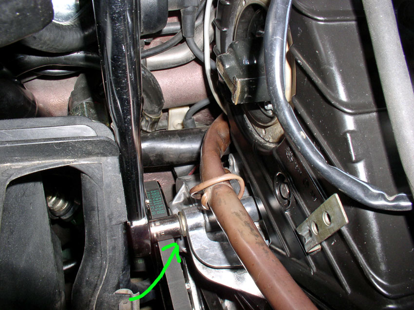
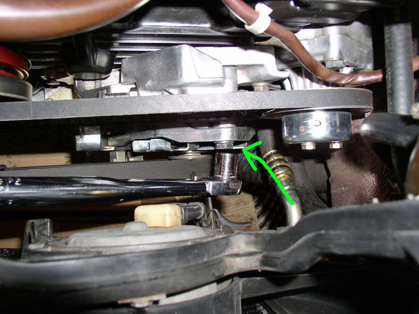
Next, loosen and remove the bolt for the support bracket for air pump and A/C
compressor. We'll be removing the air pump later when working on the timing
belt tensioner. It takes a 13mm socket as shown.
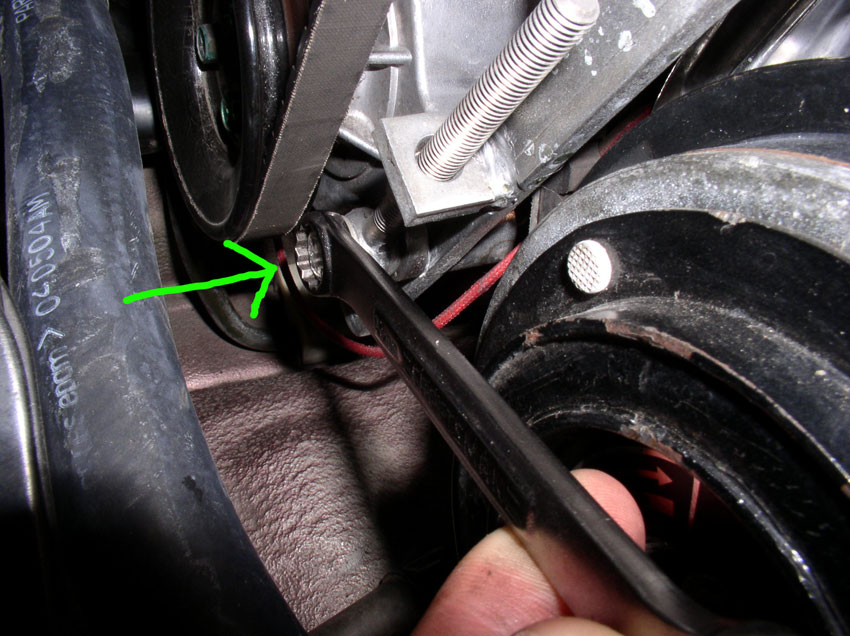
Loosen the compressor locking bolt using a 17mm wrench as shown.
Then, loosen the position adjustment nut for the A/C compressor using a 13mm
wrench. Loosen the nut enough so you can move the compressor as far as possible
in the belt-loosening direction.
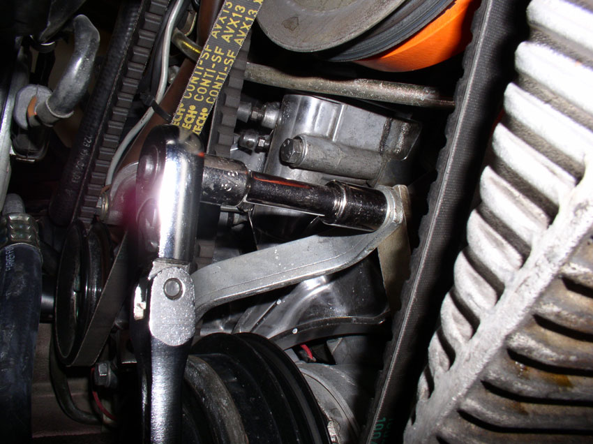
Now, loosen the Air Pump pivot bolt. It takes a 13mm wrench as shown.
Loosen the Air Pump locking bolt. It takes a 13mm wrench as shown.
Then, using a stubby 13mm wrench, loosen the adjustment nut as much as is
needed to provide enough slack in the belt to remove it.
When you have enough slack, remove the belt.
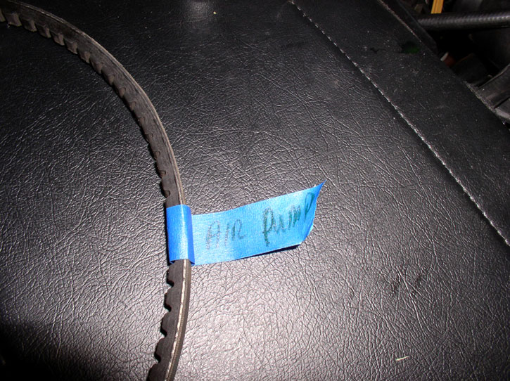
Mark the belt as to which accessory it came from. Air Pump in
this case. The remaining two belts (Power Steering and A/C) will be
removed when we remove the crank pulleys.
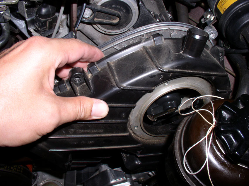
CH04 Removing Fan Shroud
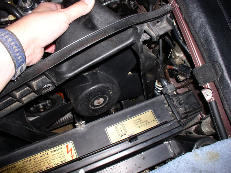
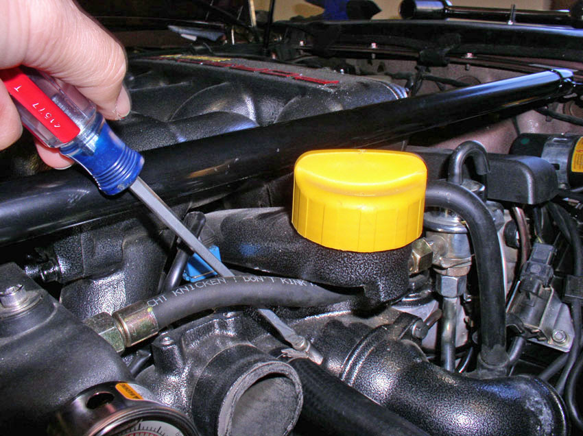
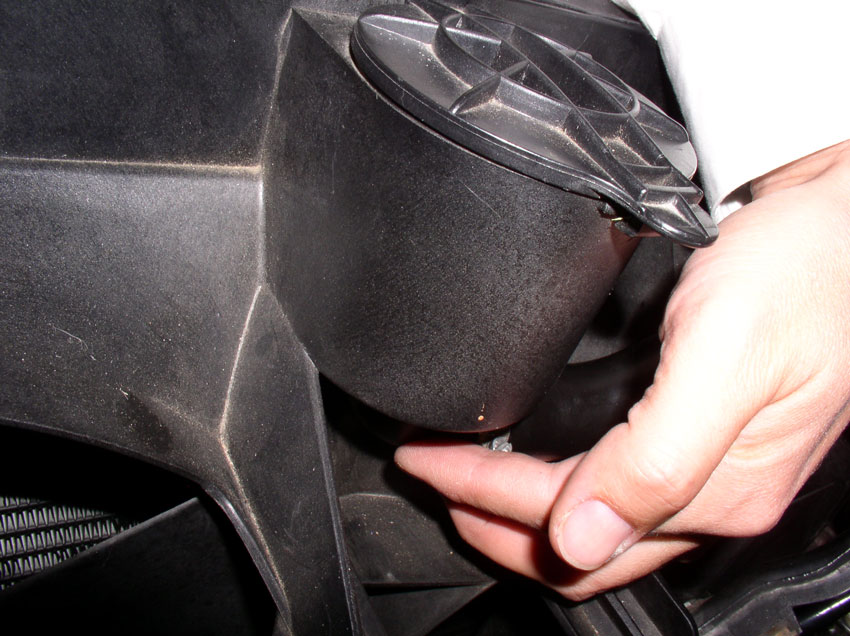
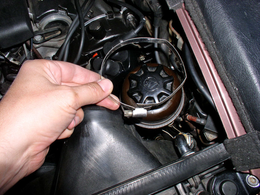
The fan shroud is a tight fit to get out so a few things need to
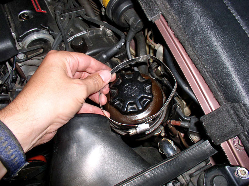
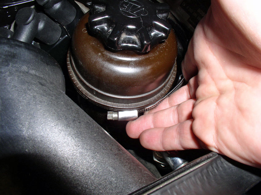
be moved in order to make room. First, loosen the clamp on the power steering
reservoir...
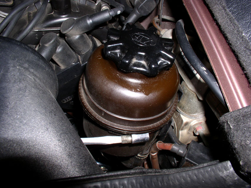
...and remove the clamp completely. The reservoir should stay upright by
itself.
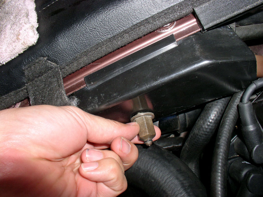
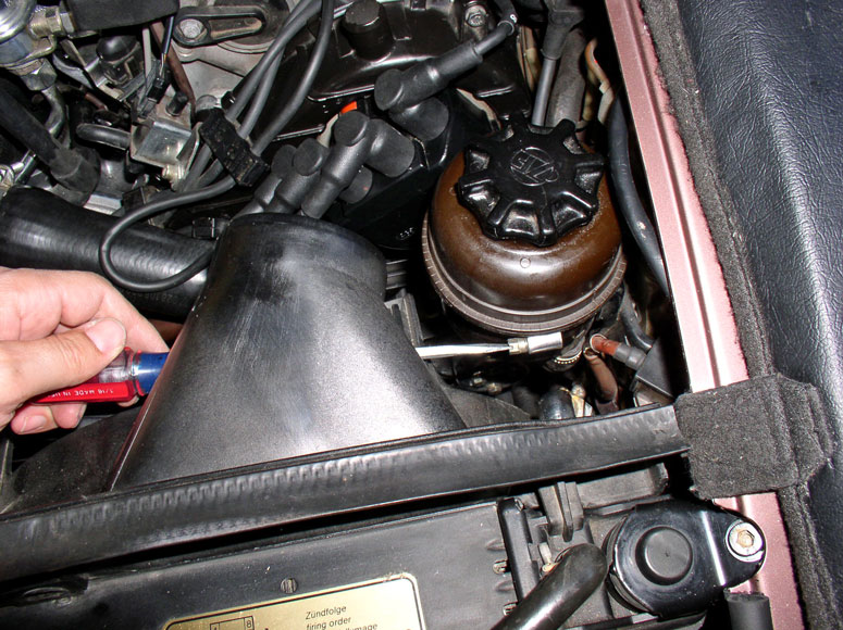
Then, remove the charging post nut cover.....
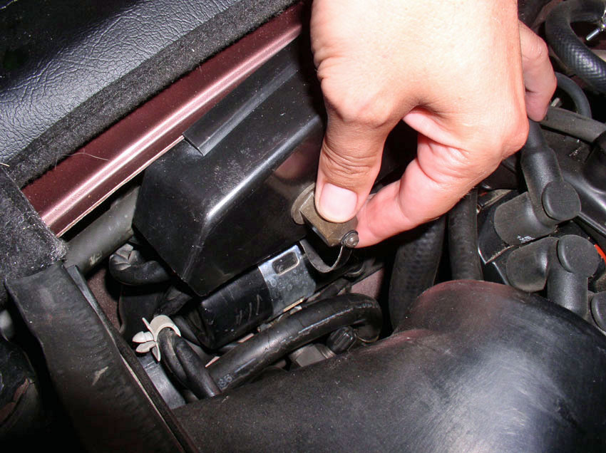
....and remove the plastic charging post cover.
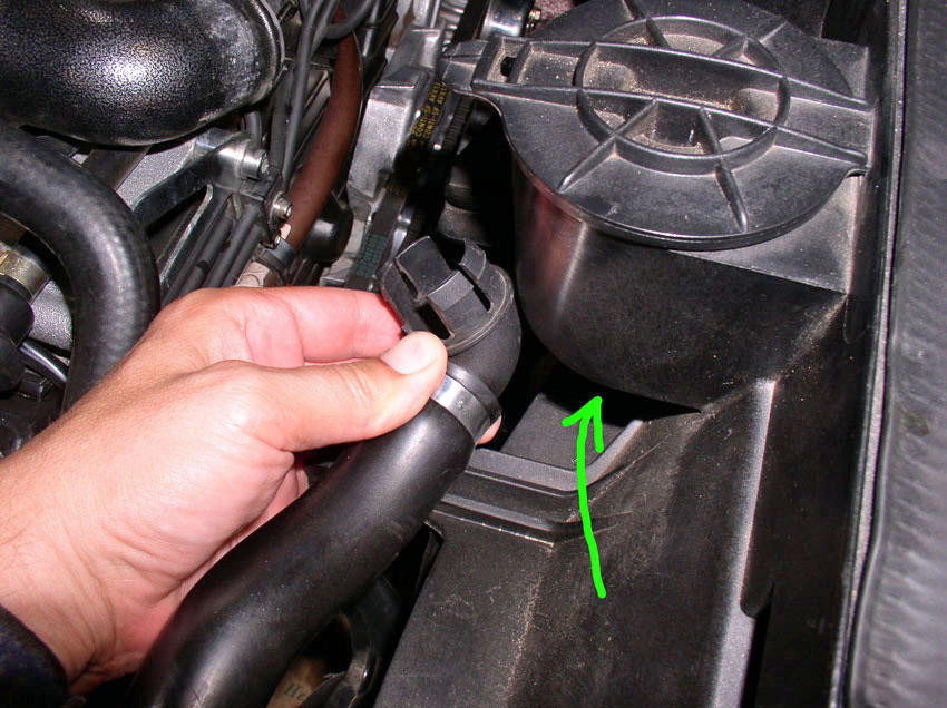
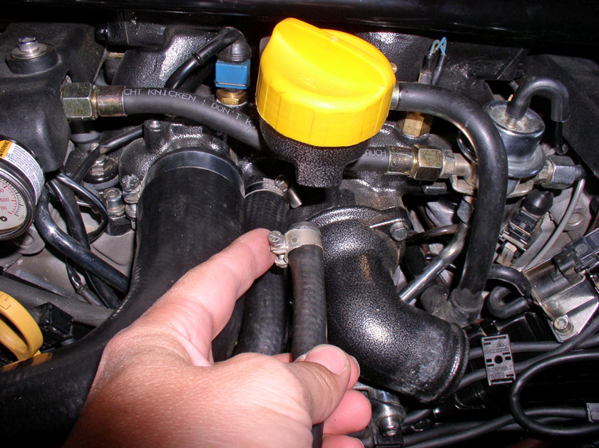
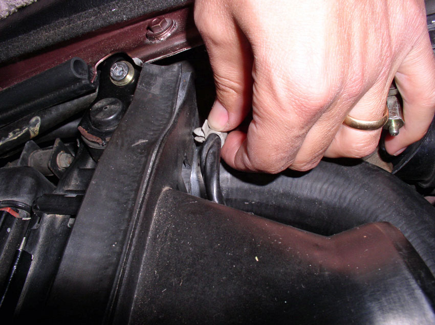
Remove the hose from the bottom of the air pump filter that's on top of the fan
shroud. You can simply pull down on the plastic elbow to remove the elbow and
hose from the filter housing.
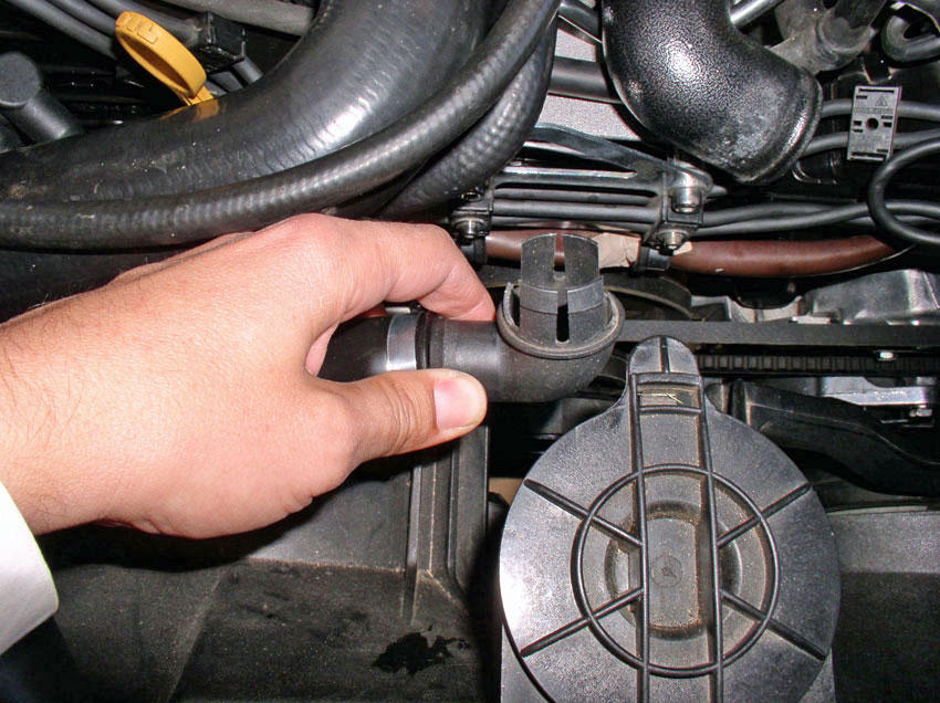
Loosen the clamp and remove the plastic elbow from the hose. This is a
precaution so the elbow won't get damaged during the next hose-contorting
procedure.
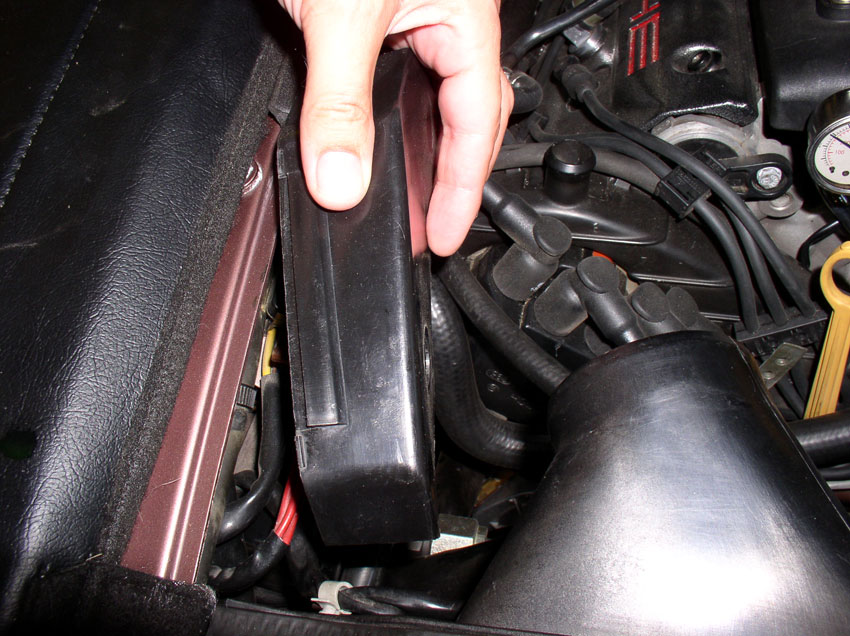
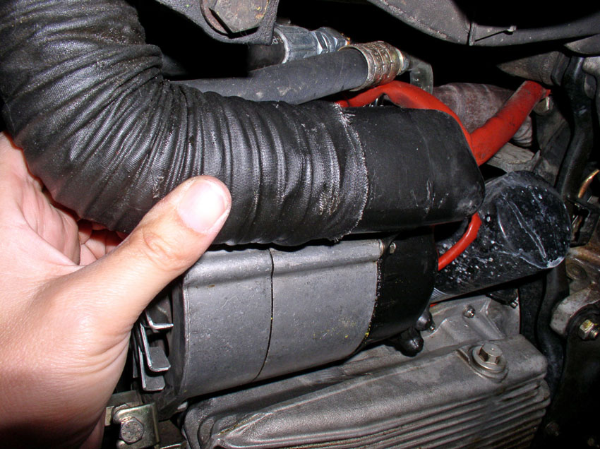
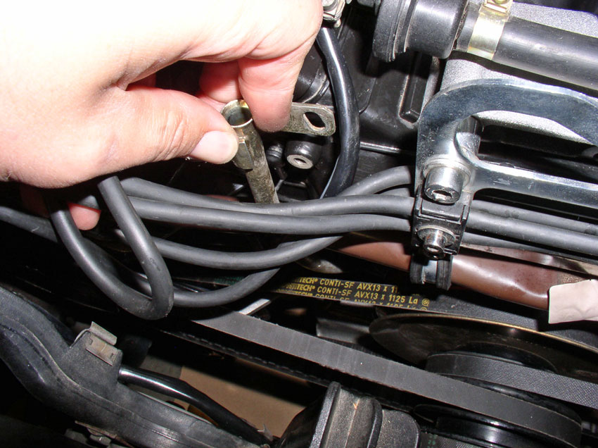
I found it easier to get the air pump hose out of the way while removing the
fan shroud so I pushed it down between the fan shroud and engine as pictured.
From underneath, you can continue to pull the air pump hose downward....
....Until the hose is pointing downward as shown.
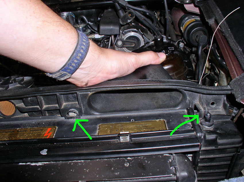
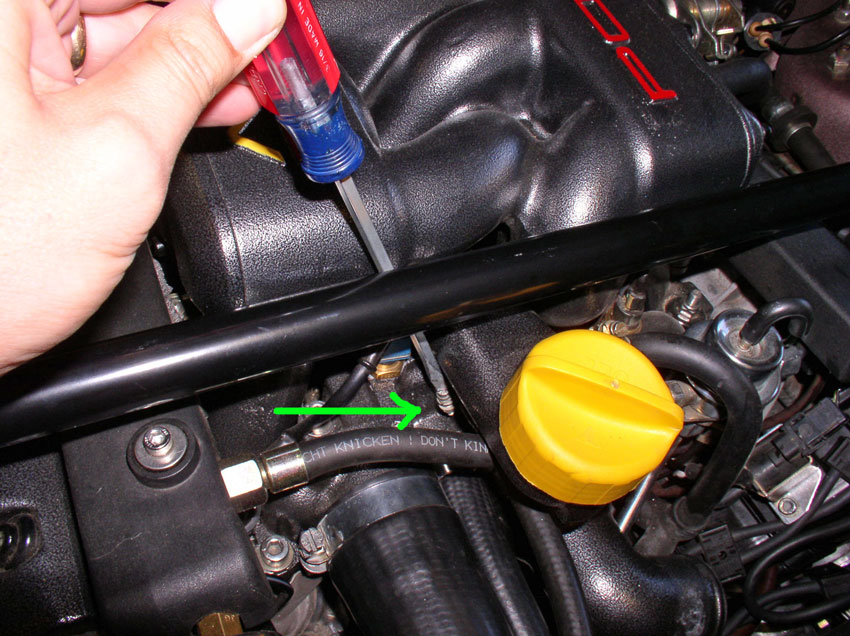
Next, remove the two 10mm screws that secure the top of the fan shroud to the
top of the radiator.
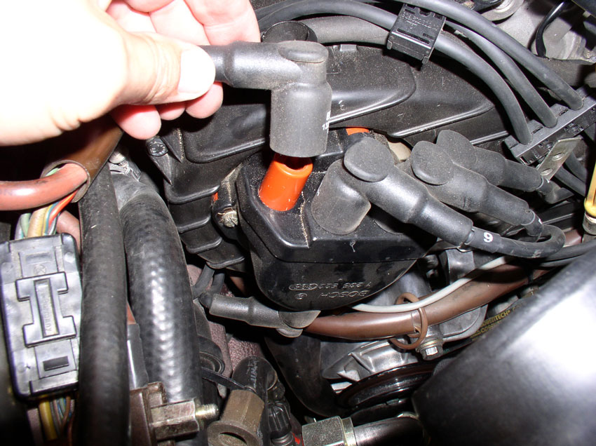
Although probably not necessary to remove the fan shroud, I removed the
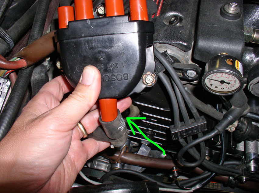
distributor caps anyway since I would have to remove them later on. First,
remove the spark plug wires from the distributor.
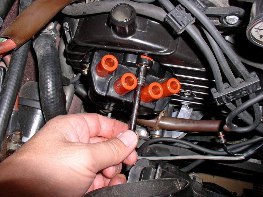
Then, remove the cap by completely loosening the 3 screws that secure the cap
to the cam cover. I used a flat blade screwdriver on the top screw.
...and on the bottom right.
But I used a 8mm socket on the bottom left screw.
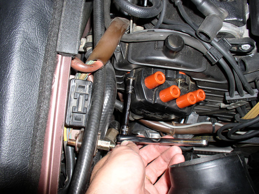
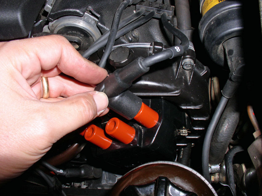
Once you have the cap off, remove the coil wire from the bottom of the cap.
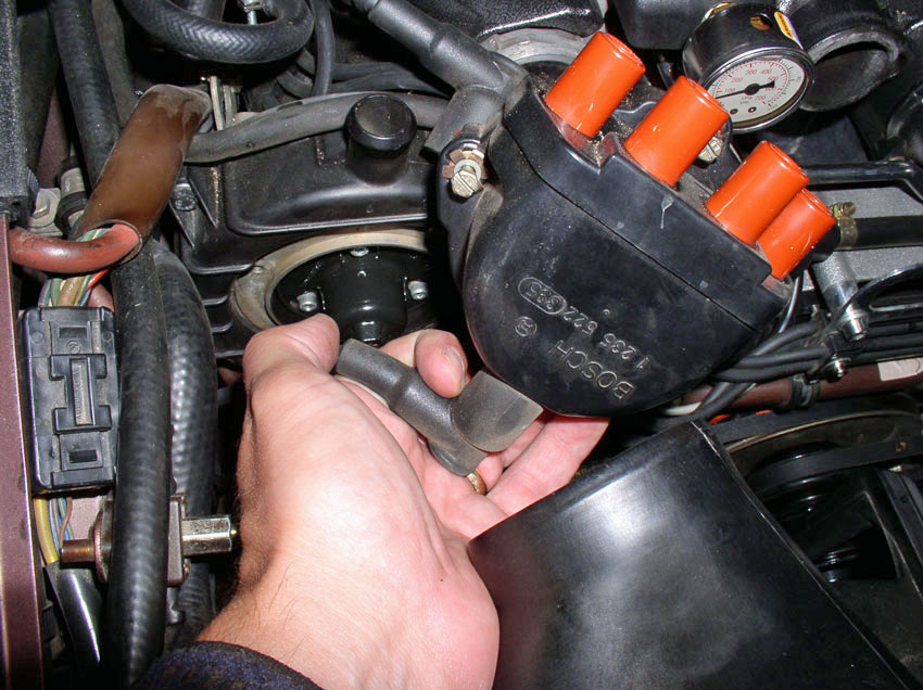
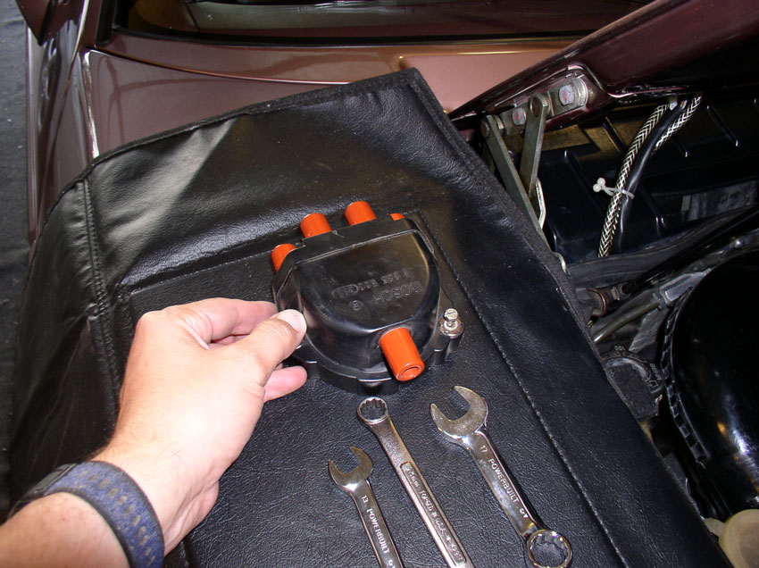
Set the distributor cap aside. I place it on the fender service cover
corresponding to the side of the engine it came from. Perform the same
operation on the distributor cap for the driver's side.
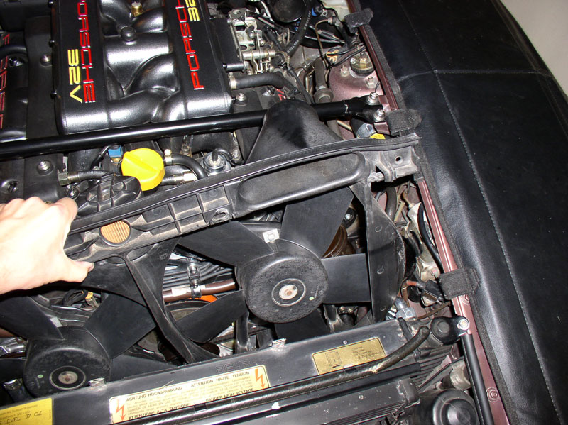
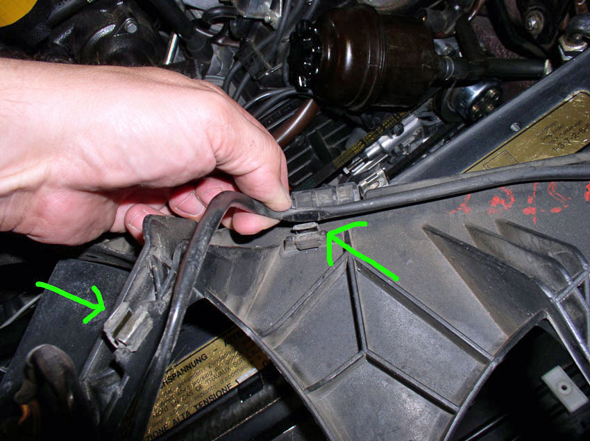
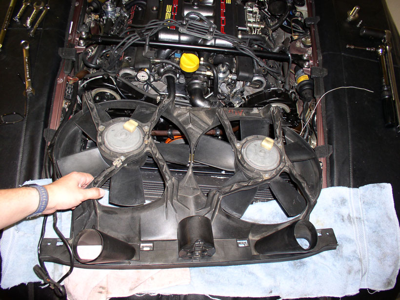
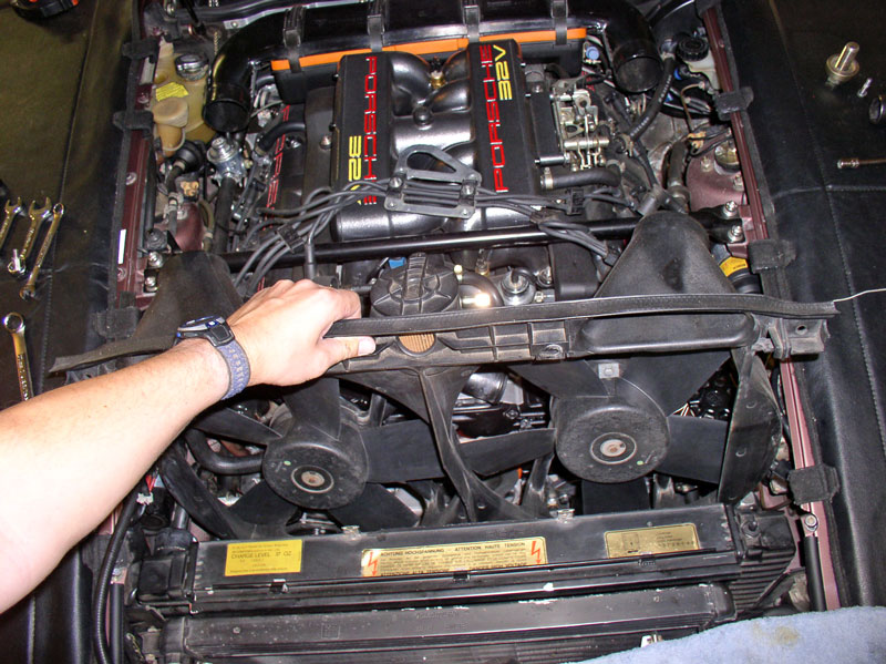
To remove the fan shroud, first pull the shroud up an inch or two - this should
clear the two locking tabs on the front of the shroud.
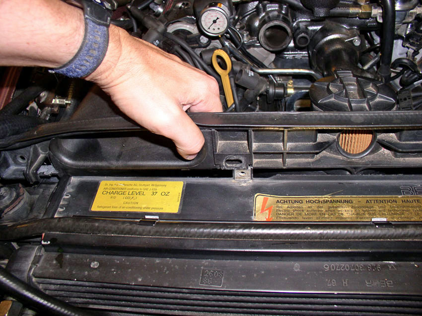
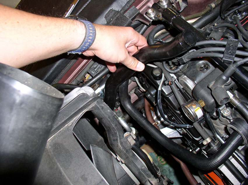
Then, push the right hand side of the shroud back enough to clear the top oil
cooler line and nut as pictured below.
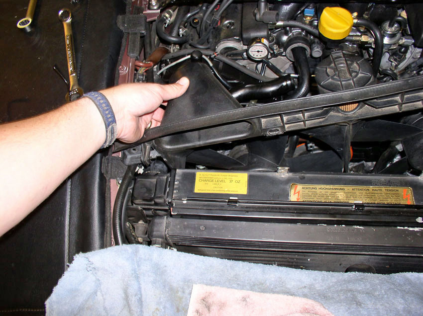
Next, pull up on the right hand side of the shroud enough to clear the
obstacles on the right hand side of the engine bay. Then you should have enough
room to pull the left hand side up and out.
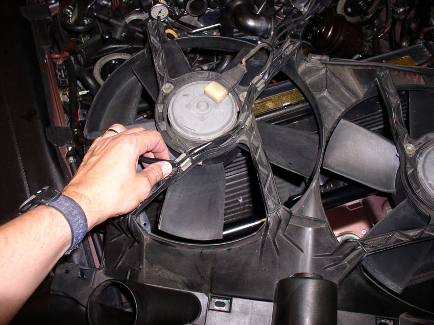
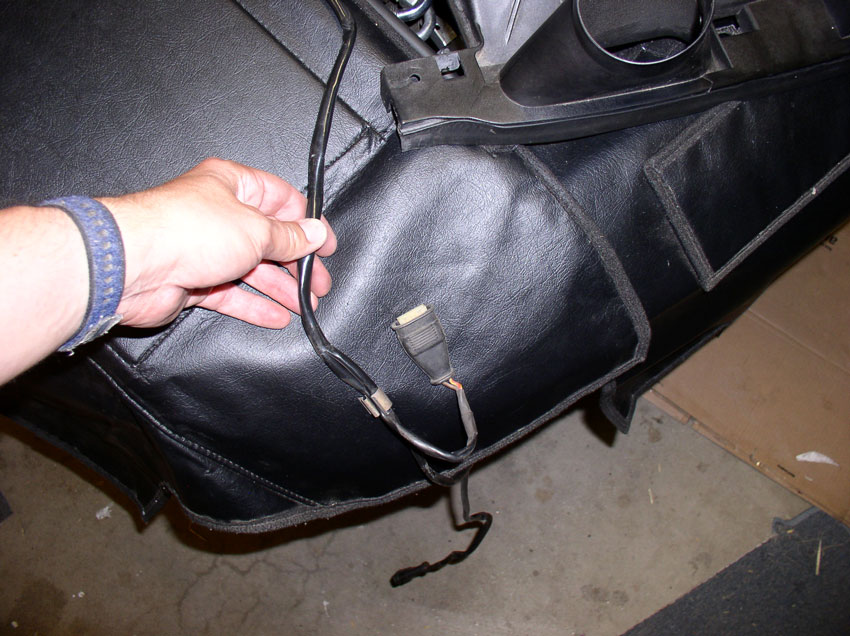
Lay the fan shroud face down (with backing exposed) across the top of the
radiator as shown. Remove the wiring harness from the first few harness clips
as shown.
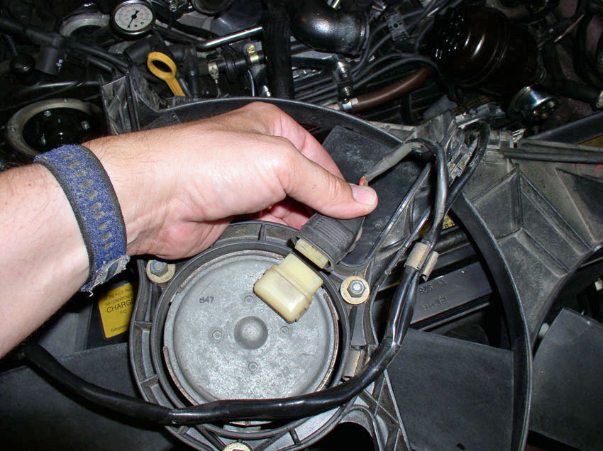
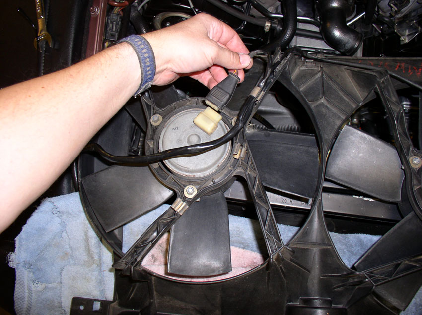
Pull both of the harness plugs from the fan motors.
Remove the wiring harness from the remaining harness clips as shown.
With the harness completely disconnected from the fan shroud, lay the harness
aside and place the fan shroud out of the immediate work area.
I then tied the PS reservoir with some string to keep it out of the way.
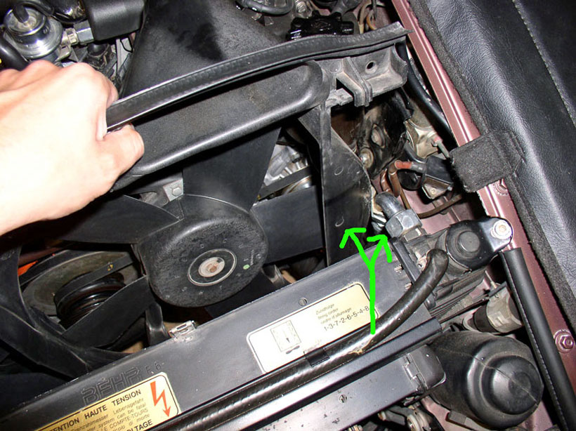
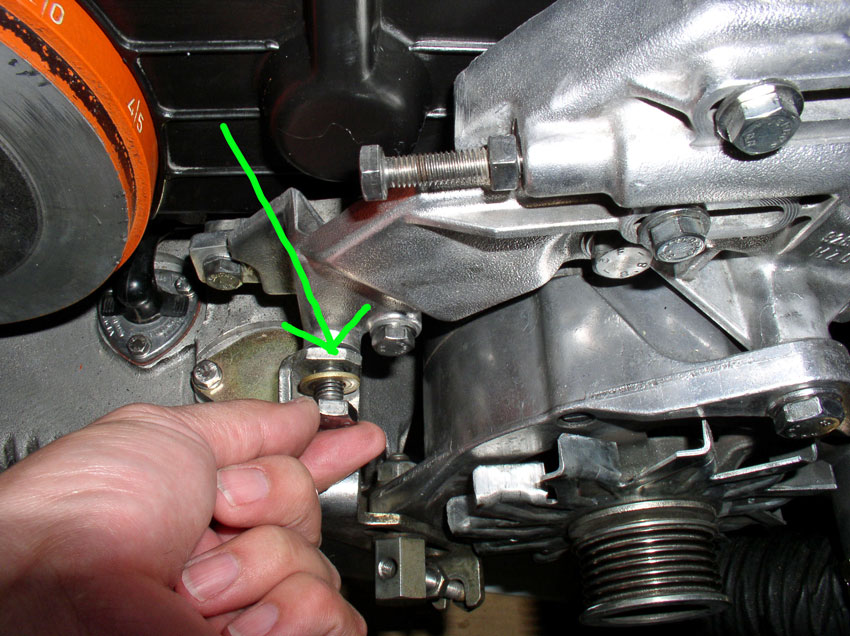
CH05 Removing Power Steering
Pump and Alternator
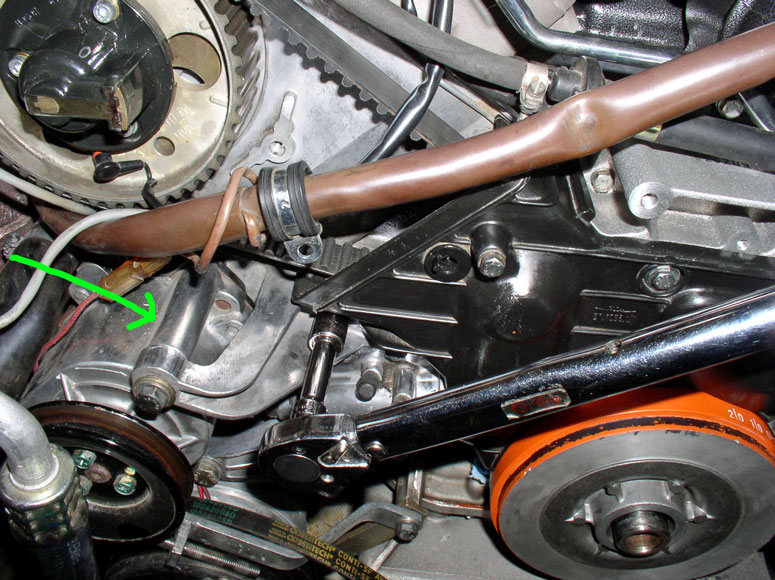
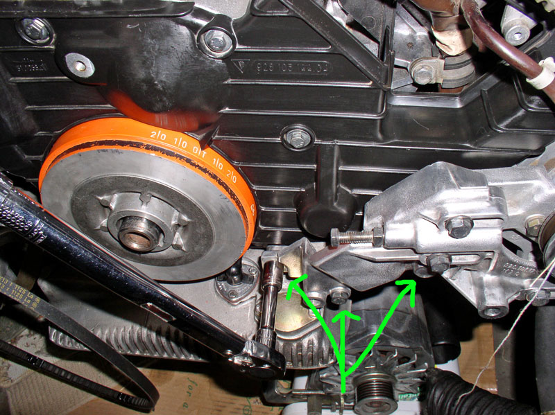
The Power Steering Pump belt tension is locked in place by the two
13mm bolts pointed at by the two green lines below. The pump is allowed to
slide left or right toward minimum and maximum tension. The adjusting bolt is
also locked in place by a locking nut pointed at by the green arrow below.
First, loosen the lock nut. It takes a 13mm wrench.

Loosen both of the sliding locking 13mm bolts as shown.
Then, using a 13mm wrench, loosen the belt tension adjustment bolt enough for
the PS pump to slide all the way back to the loosest position.
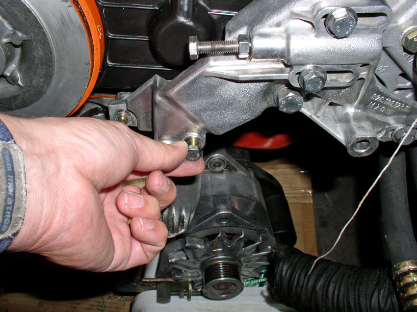
Next, we'll remove the alternator before removing the PS pump. Place a suitable
container or box under the alternator so it can rest when removed without
putting tension on the wiring harness. I used a plastic laundry soap container.
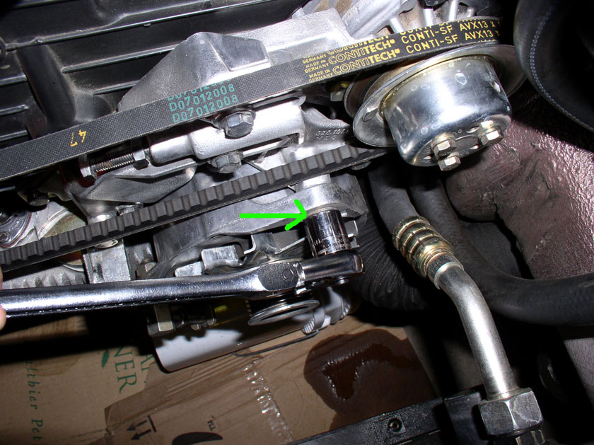
Loosen the alternator tension bracket bolt. It takes a 17mm socket and is a M10
X 25mm bolt.
Remove the bracket bolt as shown.
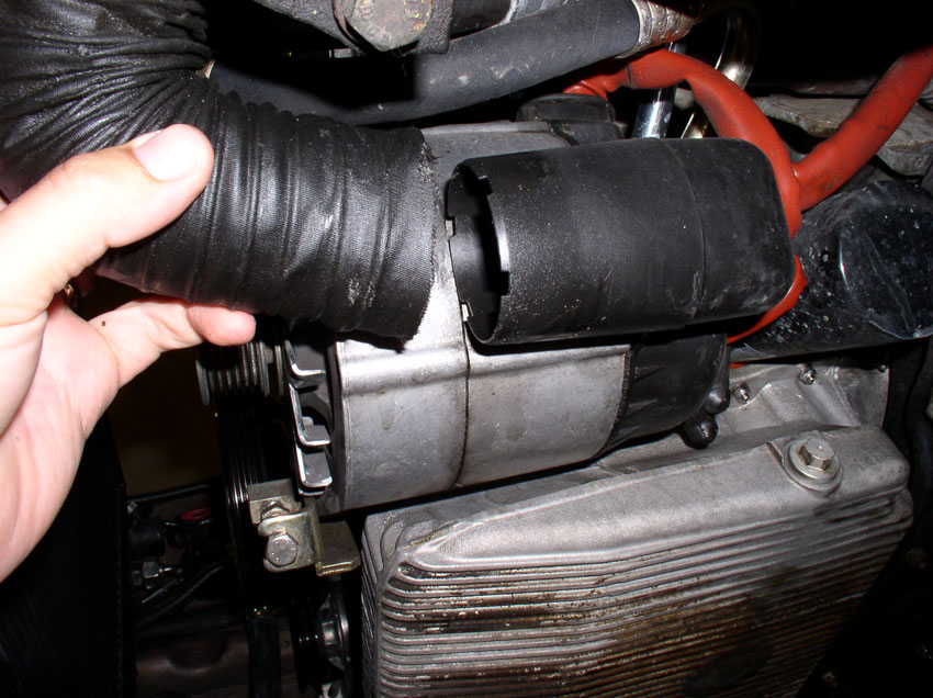
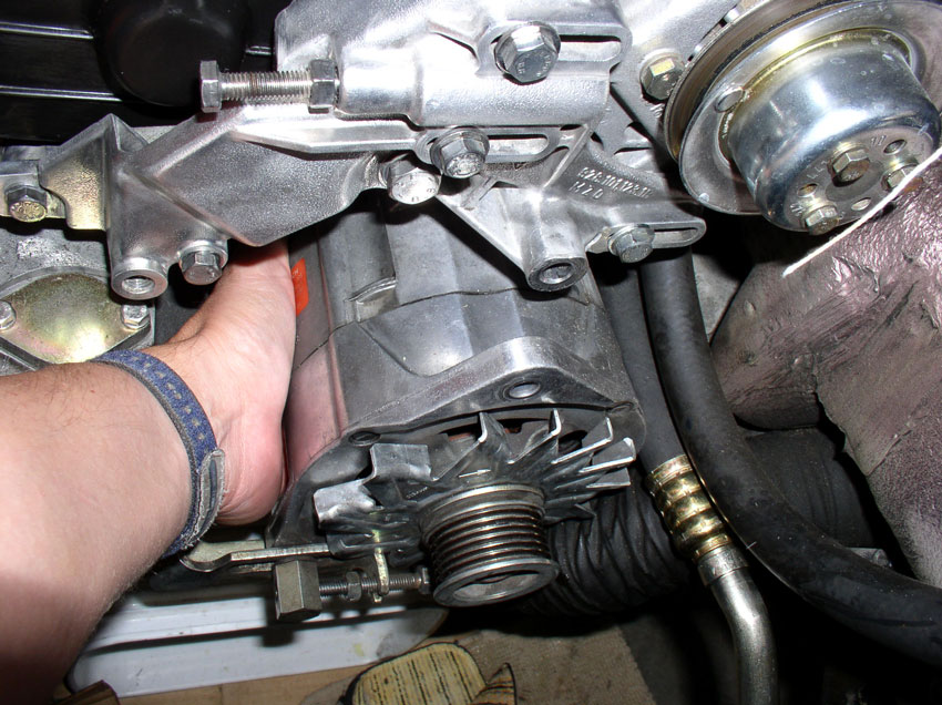
Remove the alternator cooling hose from the alternator air guide as shown.
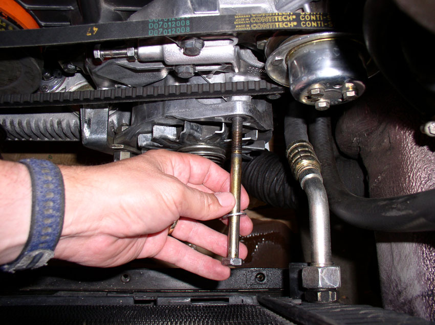
Loosen the 17mm alternator pivot bolt....
....and remove the bolt completely. It is an M10 X 130mm bolt.
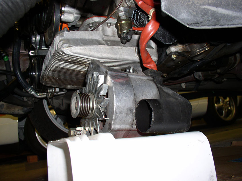
When you remove the pivot bolt, work the alternator back and forth to dislodge
it from the mounting bracket. Then lay the alternator on top of the container
as shown.
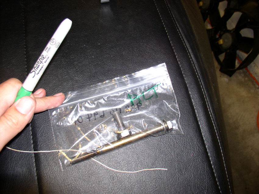
It's a good idea to bag and tag the bolts and nuts once removed. I use a
plastic zip-lock baggie for parts and mark the bag accordingly. That way, bolts
that look similar won't get misused.
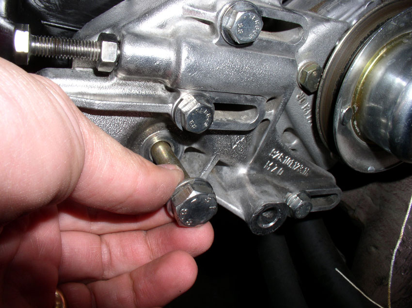
The PS Pump mounting bracket is secured to the block using 3 bolts as indicated
by the arrows in the picture. The left most bolt and middle bolt are 13mm bolts
and the one on the right is a 17mm bolt.
The middle bolt is longer than the others.
Remove the left 13mm bolt.
Remove the 17mm bolt next.
After removing the 3 PS bracket securing bolts, you can pull the PS bracket
away from the block and easily remove the belt (and mark it).
Then turn the PS bracket away from the cam cover as shown in the picture. In
this position, it provides enough clearance to get the center cam cover off.
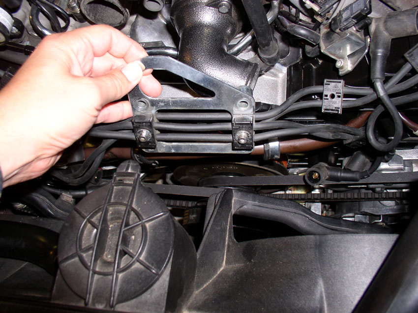
CH06 Removing
Disconnect the engine wiring harness from the center engine lift
bracket using a 5mm allen
head socket to loosen and remove the 2 harness clamps.
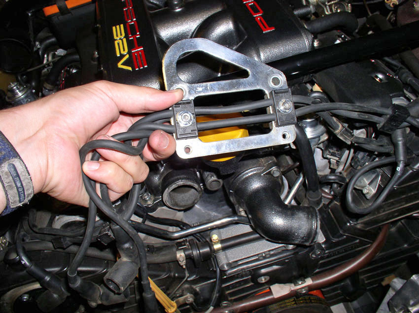
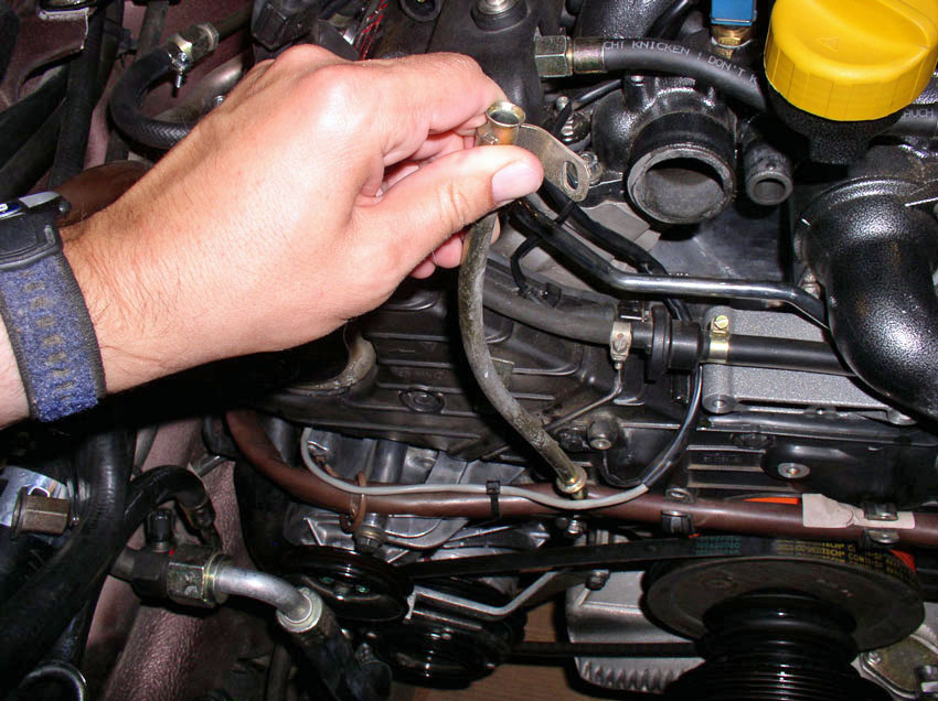
Then remove the engine lift bracket from the water pump housing by loosening
and removing both of the 6mm allen
head bolts as shown.
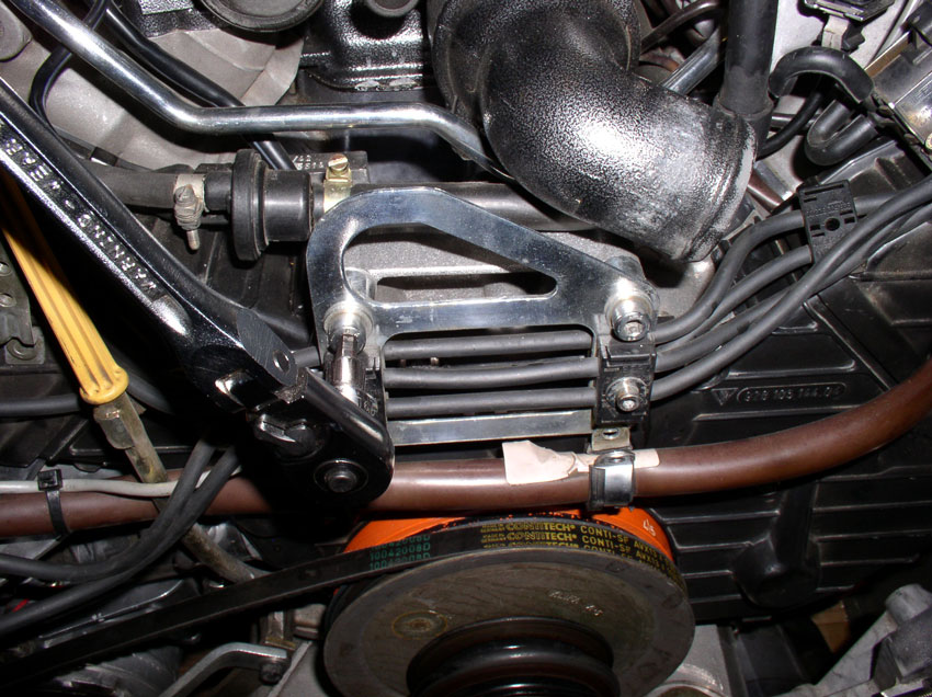
Lift the bracket up and over the oil filler neck out of the way.
Remove the oil dipstick from its tube.
Loosen and remove the 10mm bolt that secures the oil dipstick tube to the cam
cover.
Remove the oil dipstick tube by lifting up and twisting slightly. The tube has
an o-ring that seals the hole in the oil pan. If it doesn't come out with the
tube, fish it out and place it on the tube or installation later. If the o-ring looks worn or damaged, order a replacement o-ring
from one of the 928 vendors. Make sure to plug the dipstick tube hole in
the oil pan with a towel or small rag to prevent debris from entering the oil
pan.
Insert the dipstick back into the tube and set aside.
There are two 10mm bolts that hold the passenger side cam cover on. Remove the
upper left bolt as shown below.
Then loosen and remove the 2nd middle bolt as shown....
....the 2nd bolt is the longer of the two.
Remove the cam cover by lifting slightly up and out so the lip on the cam cover
clears the rear cam cover plate.
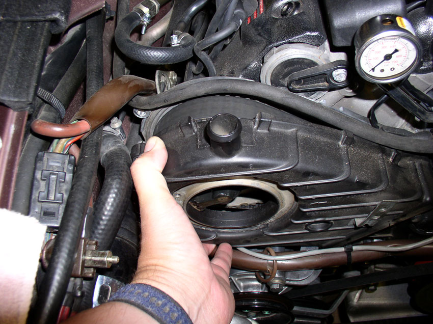
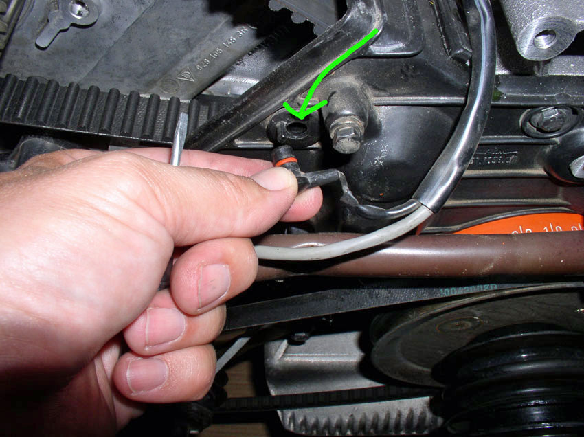
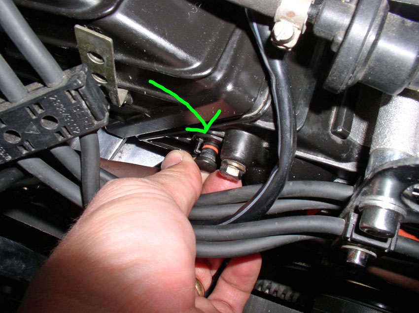
Lift the fuel vapor solenoid hose up and out of the way as shown.
Carefully pry the locking plastic tab away from the belt tension warning wiring
harness plug....
....and pull the wiring harness out of the plug as shown.
Remove the wiring harness clip from the driver's side cam cover as shown.
The driver's side cam cover is held in place by three 10mm bolts. Remove the
first one that is left and top of the driver's side cam cover and also secures
the flappy valve vacuum solenoid bracket as shown in the pic
below.
Remove the uppermost 10mm bolt next as shown.
The third 10mm bolt is located out of sight in the opening for the engine
harness. Locate and remove the bolt as shown in the pic
below.
Now you should be able to remove the driver's side cam cover.
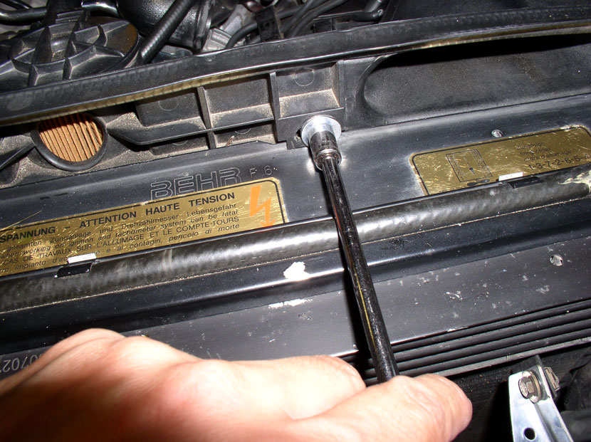
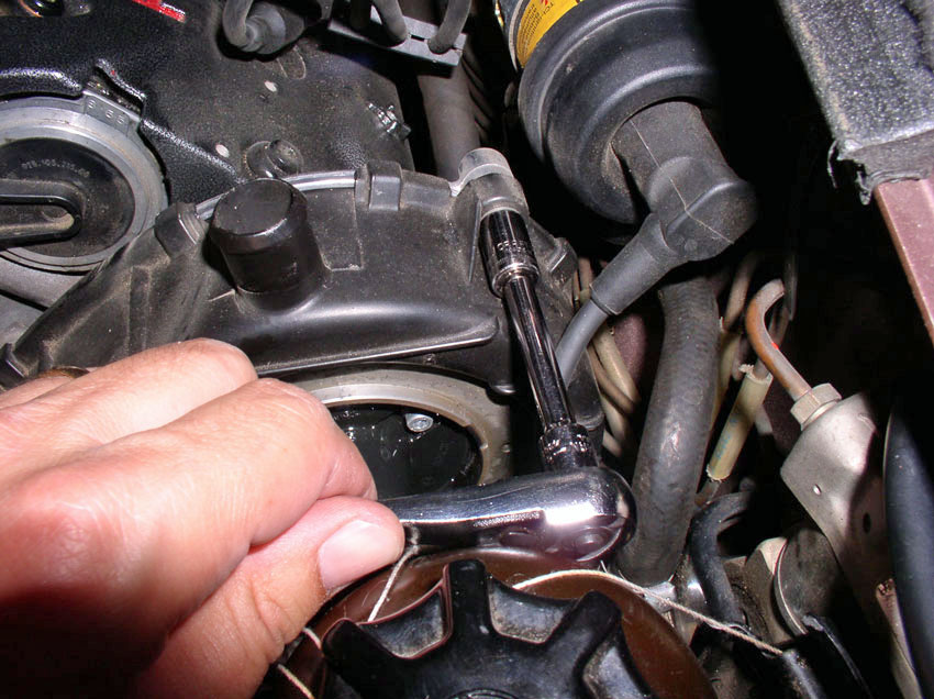
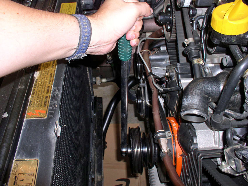
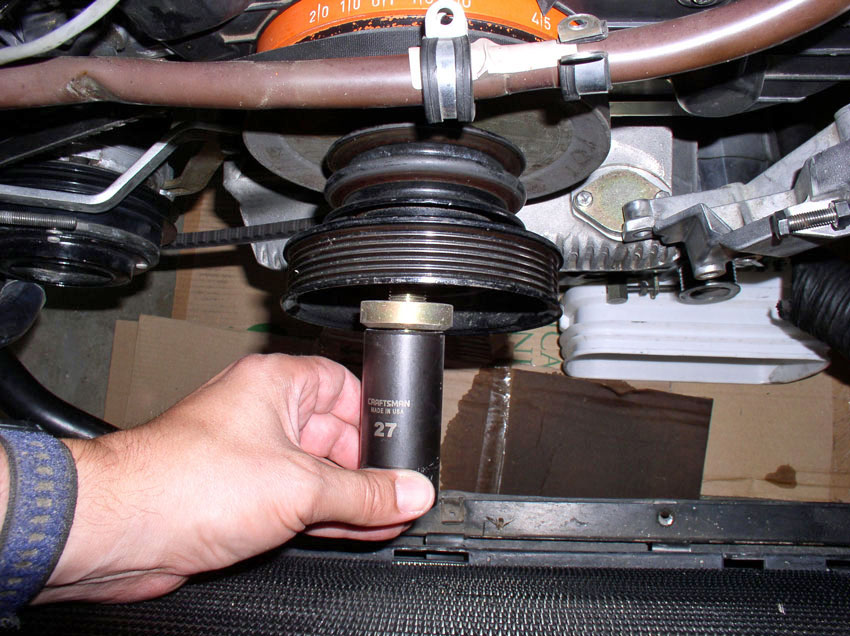
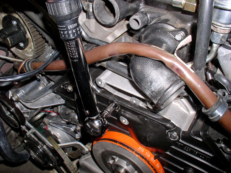
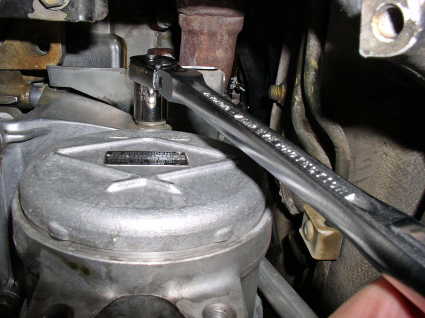
Now you will turn the engine to Top Dead Center (TDC) and check belt tightness
and alignment of cam gear timing marks. I use a tall 27mm 6-point socket....
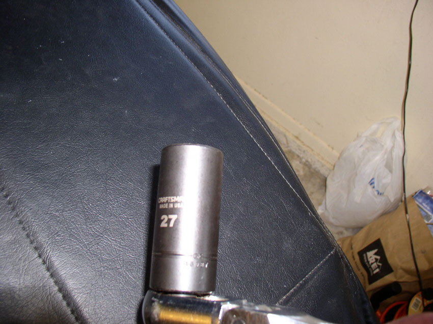
....and a long handle socket wrench to engage the crank bolt on the front of
the engine as shown below. Turn the engine clockwise until.....
....the harmonic balancer is at TDC as shown below. Keep in mind that the crank
turns 2 revolutions for every one revolution the cam gears make. Therefore, you
need to also check the cam gears position to ensure the engine is really at
TDC.
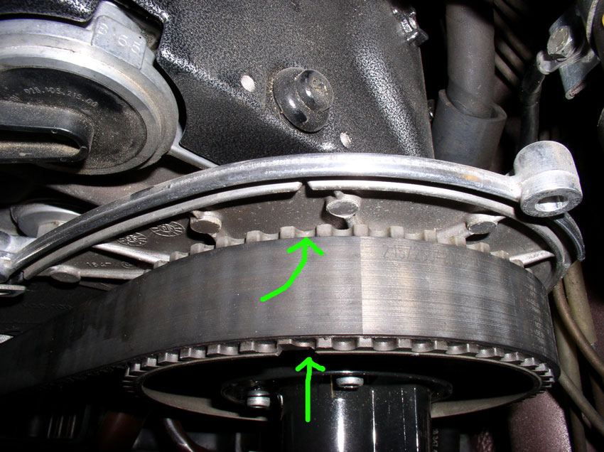
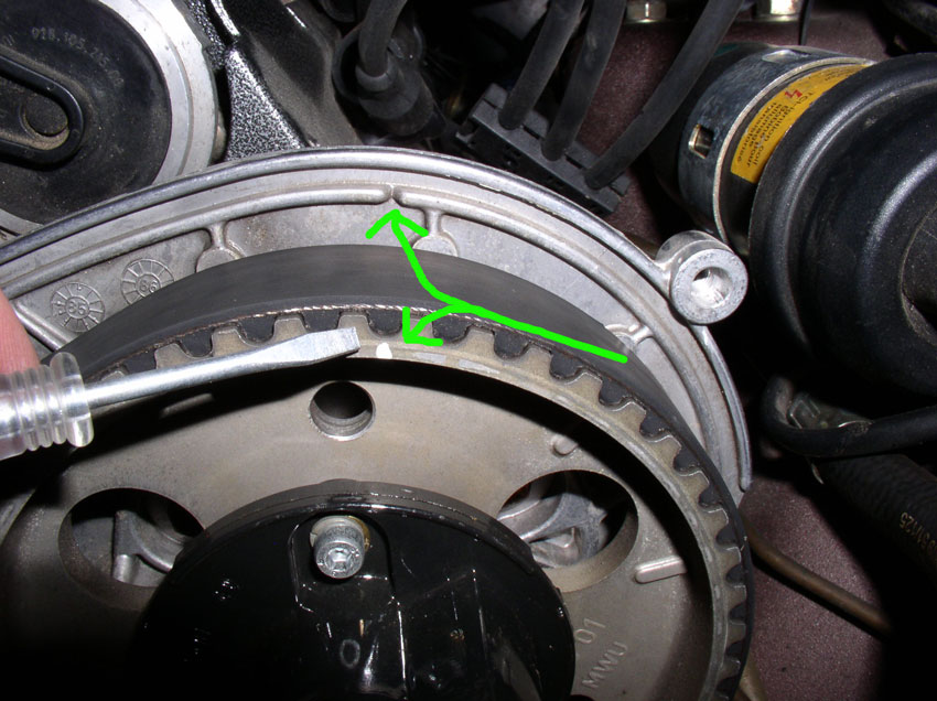
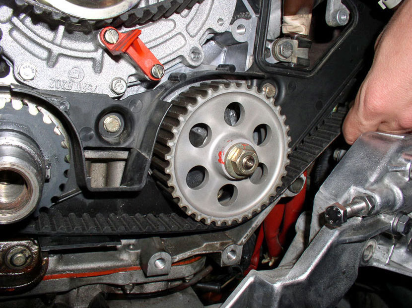
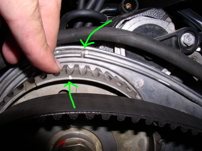
Check the cam gears when the harmonic balancer is at TDC. You should see a
"V" notch cut into the metal cam cover back plate (shown opposite the
top green arrow in the picture below). On the cam gear, you will also see a
"V" notch cut into the back side of the cam gear pointed by the top
green arrow (unfortunately, it does not show up well in this picture). There is
also a notch cut in the front of the cam gear shown by the bottom arrow in the
picture. These notches should line up very closely if not perfectly when the
harmonic balancer is at TDC. If they are not, rotate the engine another
revolution and the marks should line up.
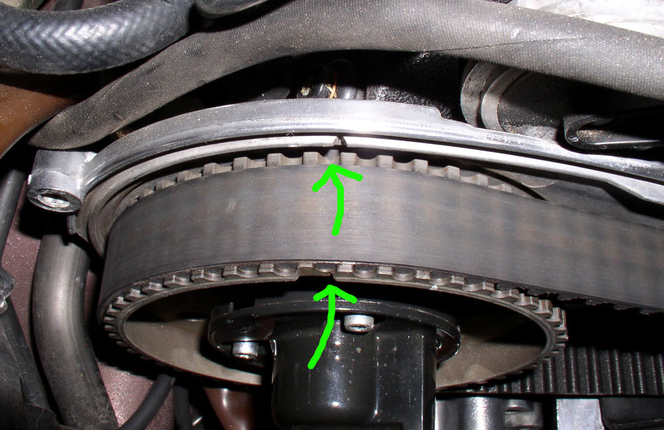
Both gears should line up the same or very close. Pictured here is the
passenger side cam gear. When the balancer is at TDC, the driver's side gear is
lined up perfectly but the passenger side gear is about 1/4 of a gear tooth off
as you can see from the photo.
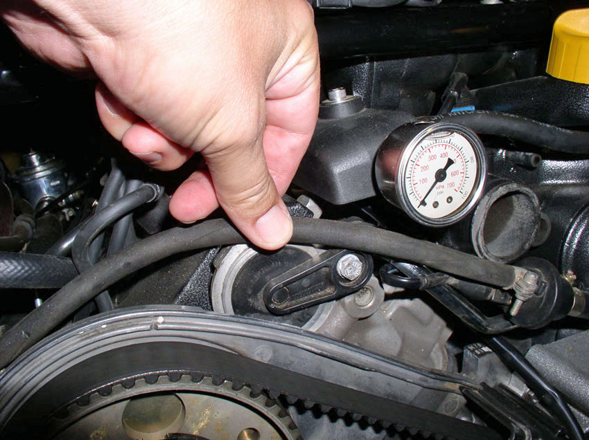
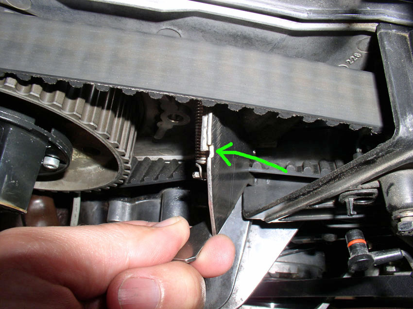
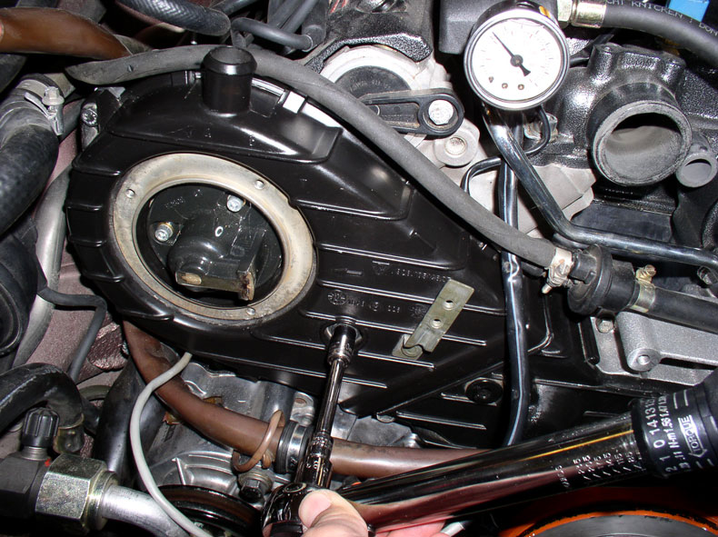
When the engine is at this position, you can check the belt tension. I checked
the belt tension just for reference to know if it was running properly
tensioned. I used the Kempf tool to measure belt tension. Place the tool as
close to the middle of the belt as you can get it (right in front of the timing
belt center cover) and measure. You can see from this measurement the belt
tension is in the middle of the tool notch - where it should be.
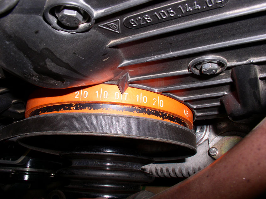
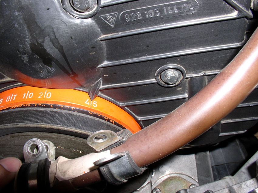
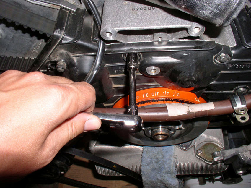
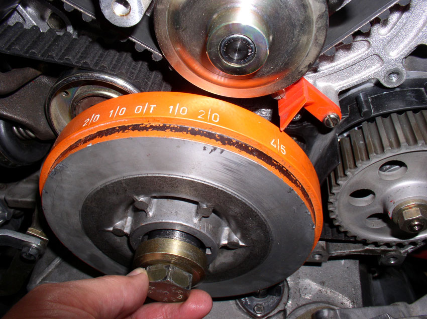
Now we need to set the crank at 45 degrees BTDC and lock the crank in place. In
this 45 degree BTDC position, it is safe to work on the timing belt as none of
the valves can contact the pistons if the cams move during the procedure. Move
the crank clockwise 1 and 3/4 turns to the "45" mark as shown.
Using the "V" notch in the cam gear back plate, mark each timing gear
with some paint as shown in the picture below. This is needed in case the gears
move while the timing belt is off. With these marks, you will be able to line
up the gears properly when installing the new belt. Mark both gears.
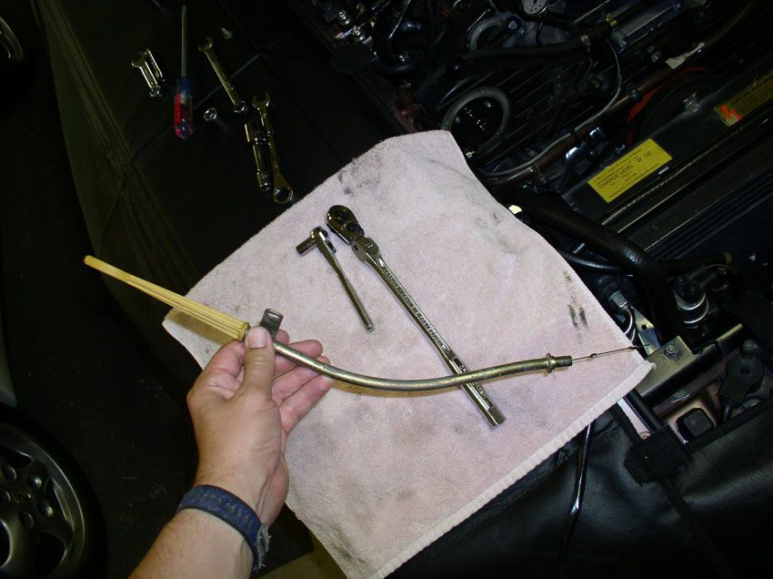
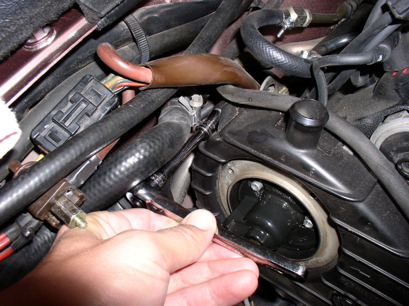
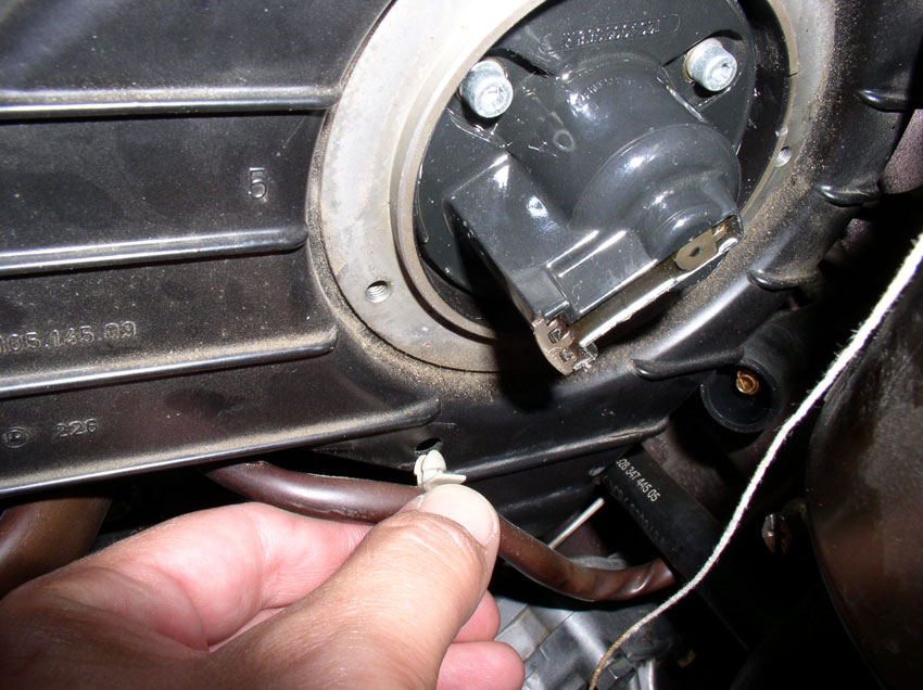
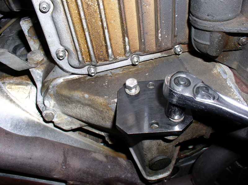
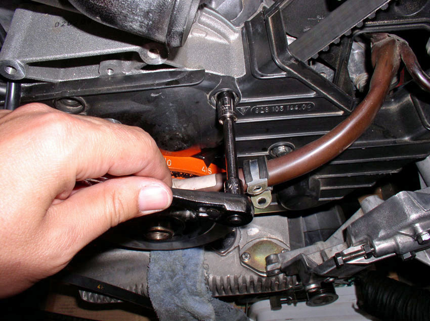
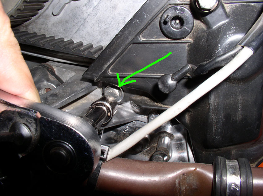
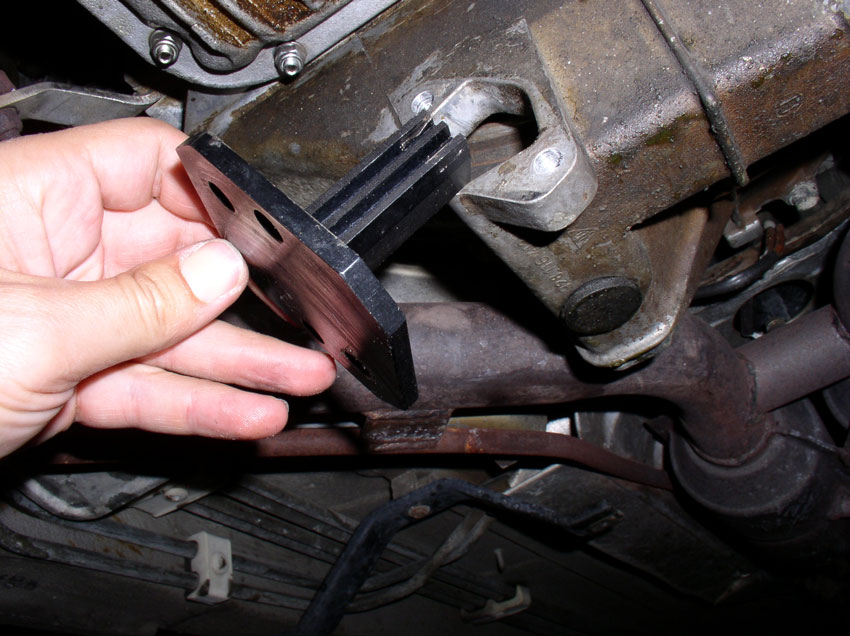
Go underneath the car and remove the flywheel inspection plate. The plate is
secured with two 13mm bolts.
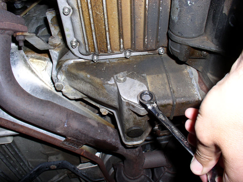
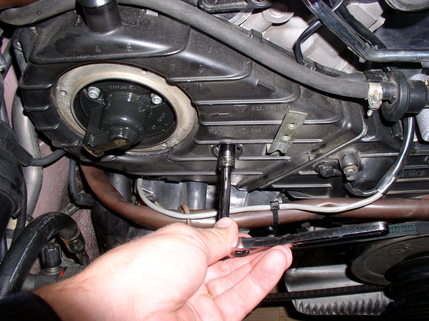
Insert the flywheel locking tool into the inspection port and secure with two
13mm bolts.
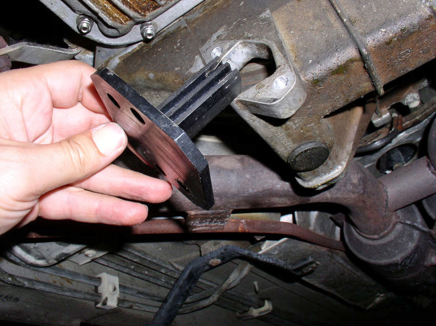
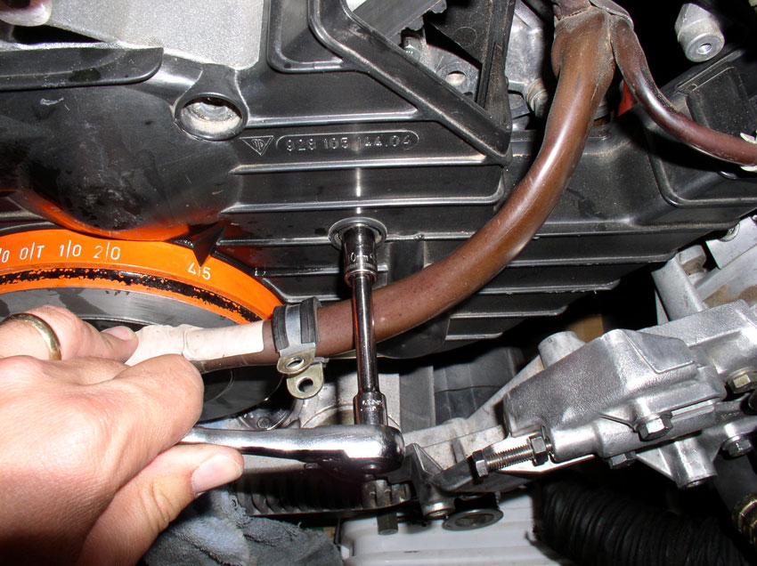
You will need longer bolts than the original 13mm bolts to secure the flywheel
locking tool. I used 13mm bolts that were about 16mm-20mm in length. Now the
engine crank is locked in place and we can remove the crank bolt and accessory
pulleys.
CH07 Removing Accessory Belt
Pulleys and Center Timing Belt Cover
With the crank shaft properly locked down, you can now loosen and
remove the crank shaft bolt. I used a breaker bar and the 6-point deep socket.
Apply force in the counter clockwise direction to break the bolt loose. If you
need more leverage, you can slide an iron pipe over the handle of your breaker
bar to give more leverage. Since I had the bolt off before, I did not need the
extension pipe for this removal.
Once the bolt is loose, remove it and set it aside.
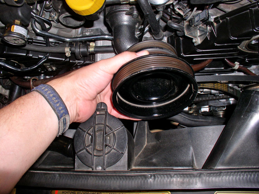
If the accessory pulleys do not come off when you pull on them, you can tap
them slightly with a rubber mallet as shown below.
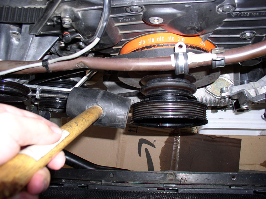
Once the pulleys are loose, remove them.
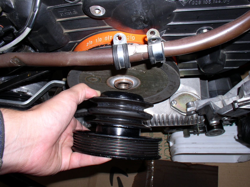
There seemed to be a little bit of rust corrosion holding the A/C pulley onto
the crank shaft. I sprayed a little aero-kroil
lubricating spray and let is soak in a few minutes.
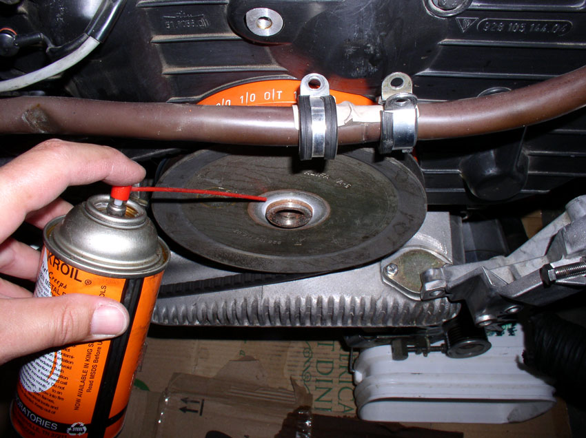
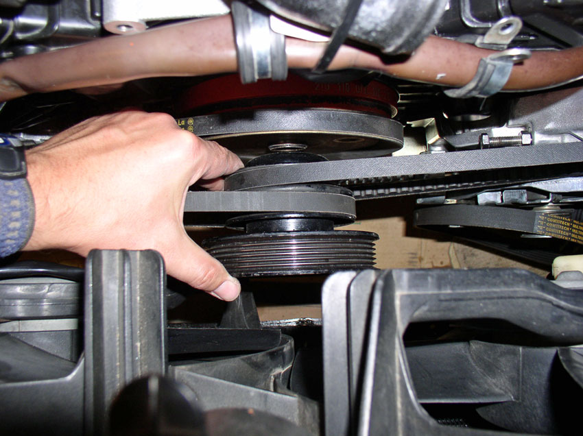
It still wouldn't budge so I put the crank bolt back in and applied a 3-jaw
puller to the pulley.....
....and it came right off. Remove the belt from the pulley and set the pulley
aside. You do not have to remove the belt from the A/C compressor. Just lay it
out of the way.
Next, we can remove the center timing belt cover. It is secured with three 10mm
bolts and a 13mm bolt. Remove the upper left 10mm bolt as shown.
Followed by removing the upper right 10mm bolt.
Then remove the center 10mm bolt. This is a long bolt and runs through the
water pump housing.
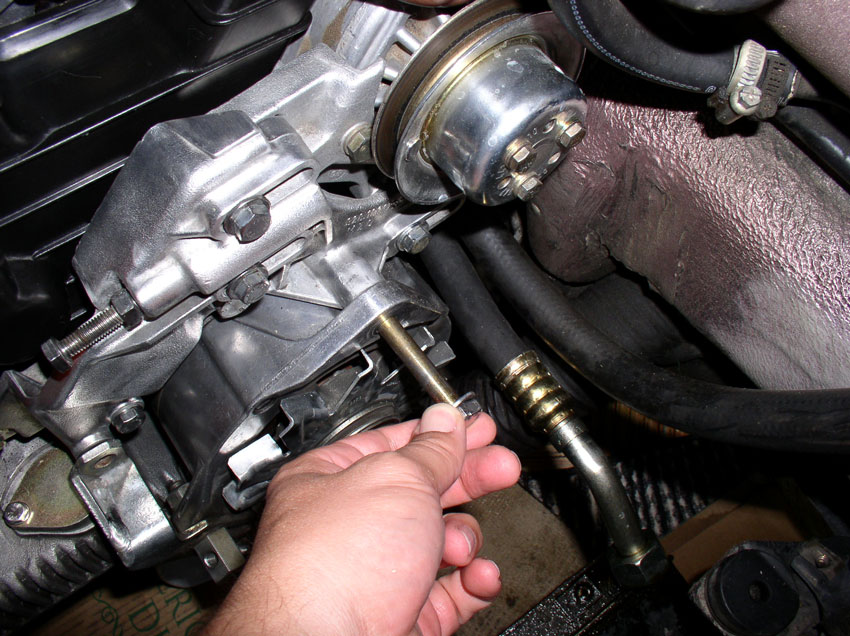
Lastly, remove the 13mm bolt that goes through the timing belt tensioner
bracket.
Now you should be able to move the center timing belt cover out just a couple
of inches. Just enough to.....
....get access to inside the cover to disconnect the belt tensioner wire from
the tensioner pivot arm as shown below.
Now, remove the center cover and set aside.
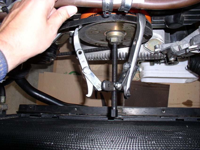
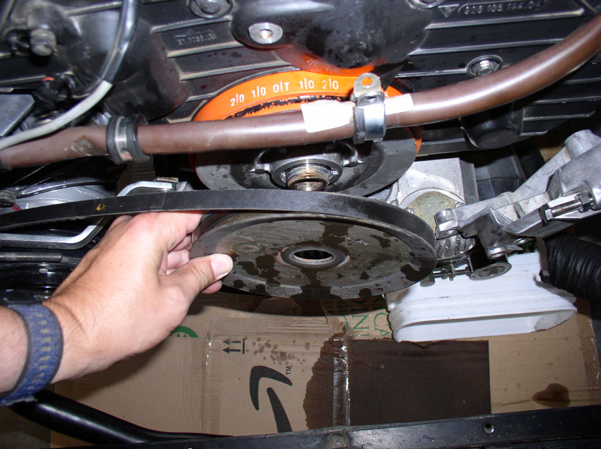
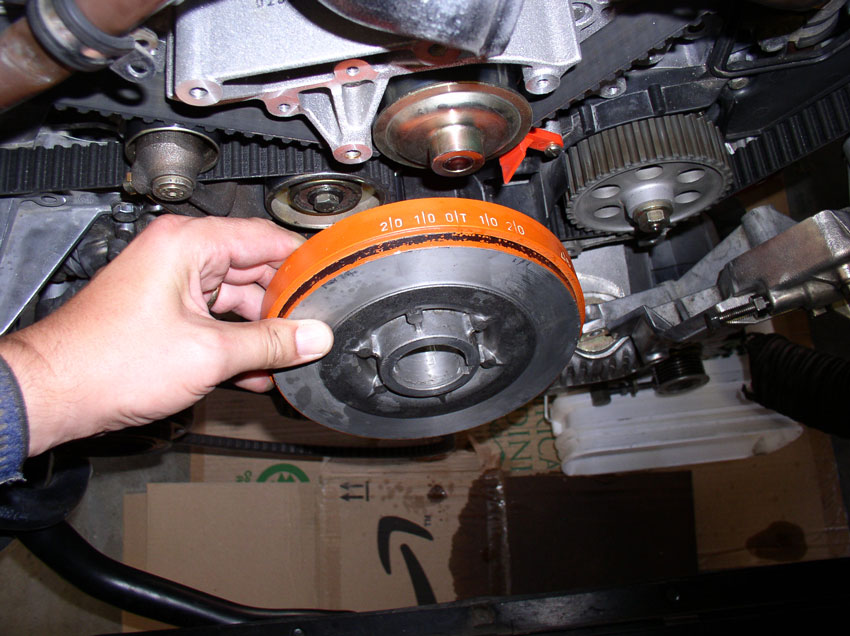
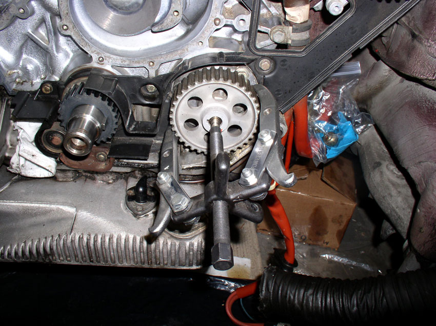
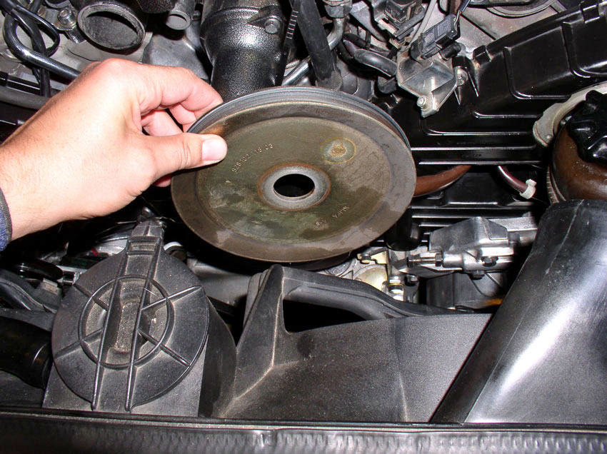
Next, remove the harmonic balancer from the crank shaft. Mine would not come
off by hand so I installed the crank bolt and applied the 3-jaw pulley puller.
After applying the 3-Jaw pulley puller, the harmonic balancer came right off!
Remove it and set it aside.
Next we'll work on removing the timing belt tensioner pulley and timing belt
CH08 Removing Tensioner Pulley
and Timing Belt
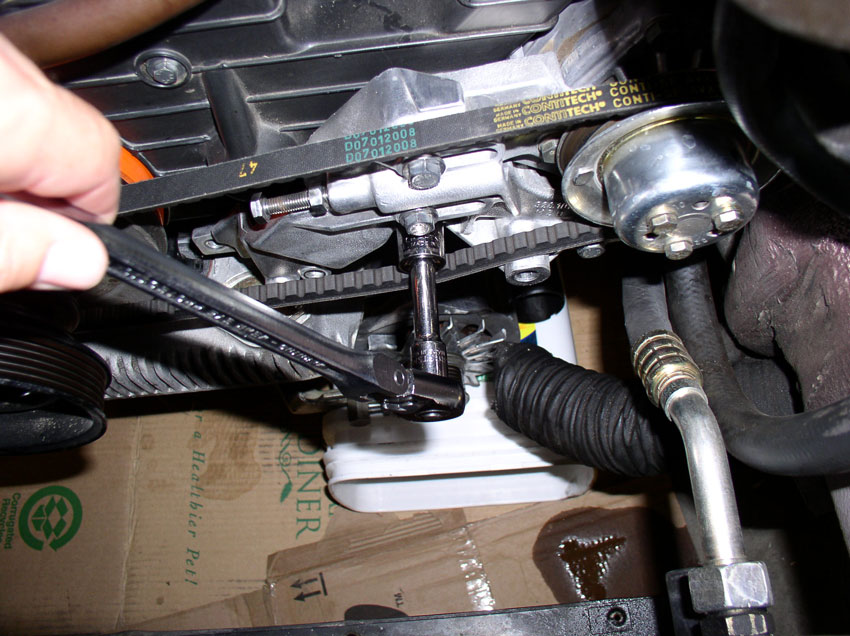
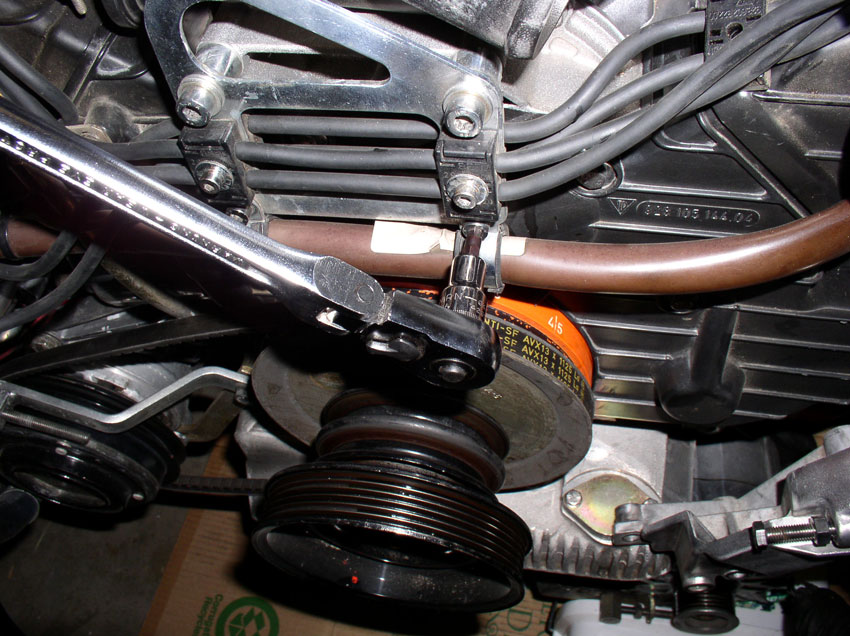
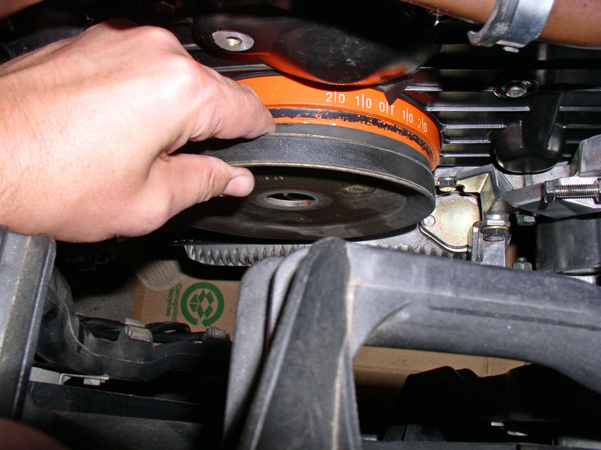
First we need to relax the tension on the timing belt. Belt
tension is adjusted using the adjustment bolt at the rear of the tensioner. The
adjustment bolt is locked in place with a locking nut. The nut and bolt are
both 17mm. Using a 17mm wrench, loosen the adjustment
bolt locking nut as shown below.
Then loosen (counter clockwise) the tension adjustment bolt. Turn it several
turns counter clockwise until.....
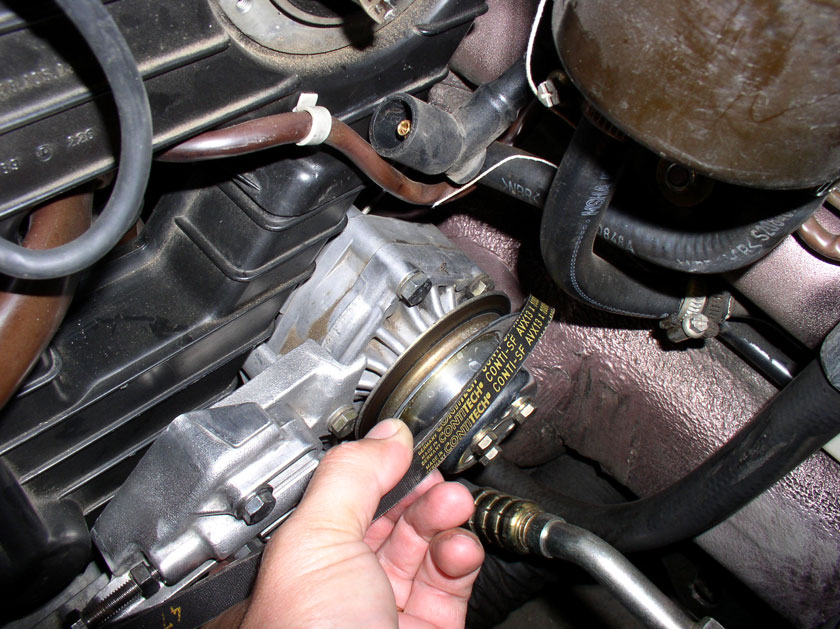
....you have some slack in the timing belt as shown below.
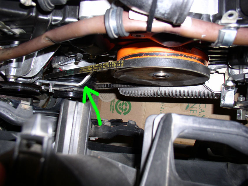
Then you should be able to slide the belt off the passenger timing gear as
shown below.
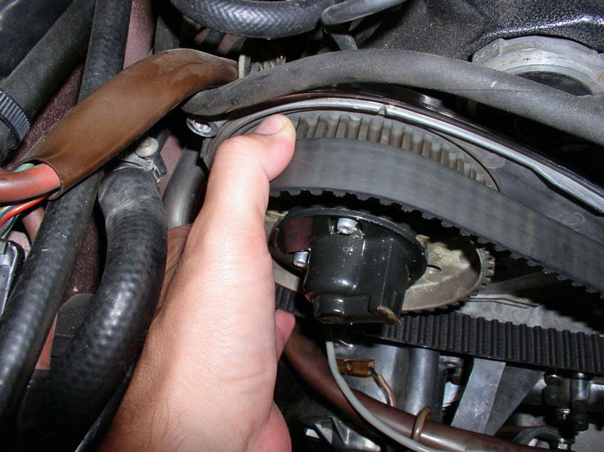
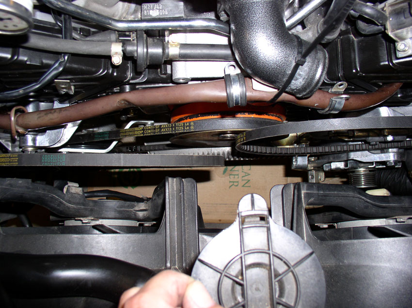
Once the belt is off the passenger timing gear, you should be able to remove
the tensioner pulley assembly. The pulley assembly is secured using a small 4mm
allen head bolt. These can
strip easily if they are stuck so be careful when removing the bolt making sure
the allen socket is secure and fully seated in the
bolt.
Remove the bolt and washer as shown.
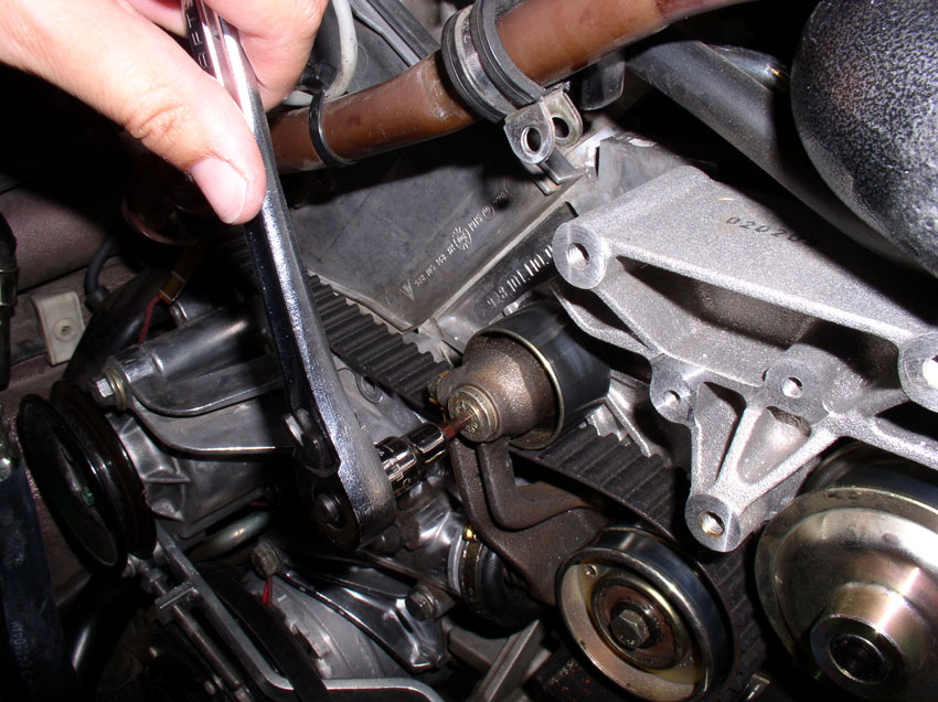
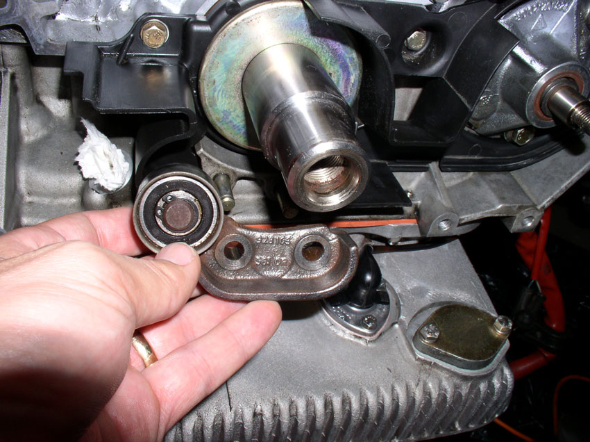
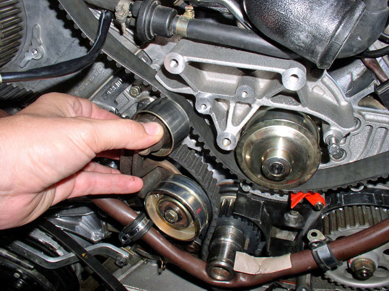
You should be able to pull of the tensioner pulley assembly. However, if your tensioner
pulley assembly is stuck on the spindle as mine was, you may
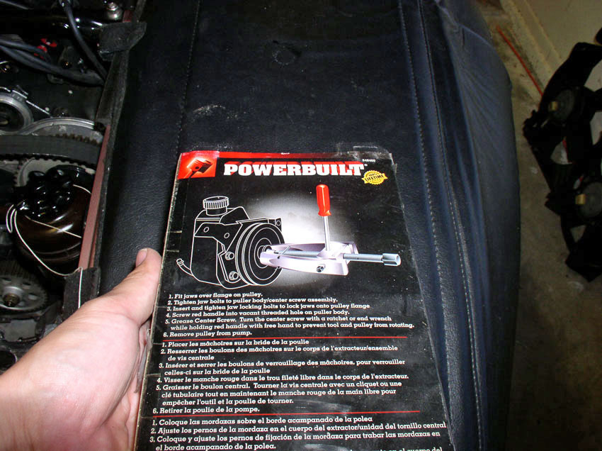
need some help getting it off. I used this Power Steering Pulley Puller
to get a grip on the idler pulley and pull the assembly off the spindle. It's a
common tool and can be found at most automotive stores.
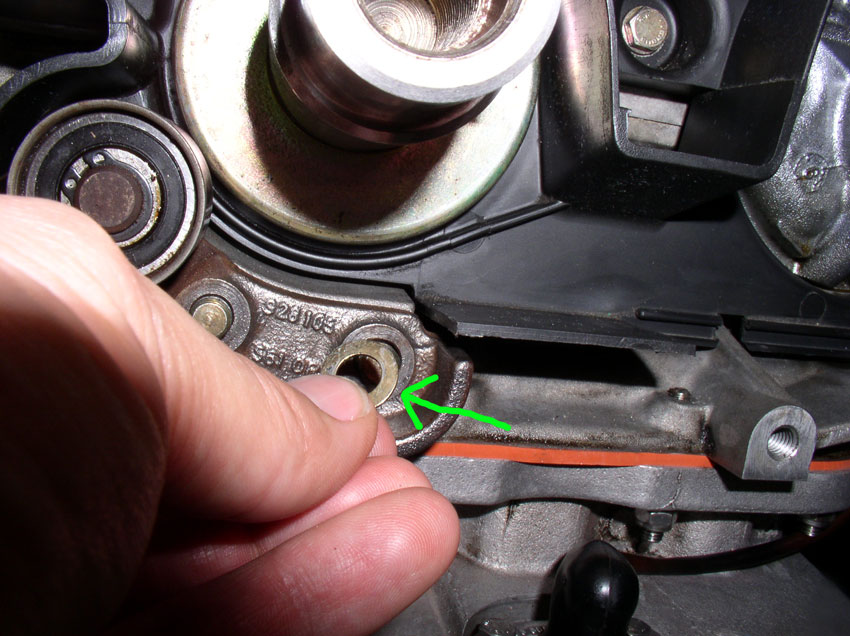
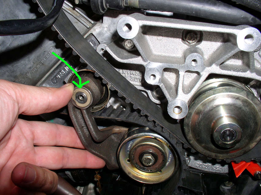
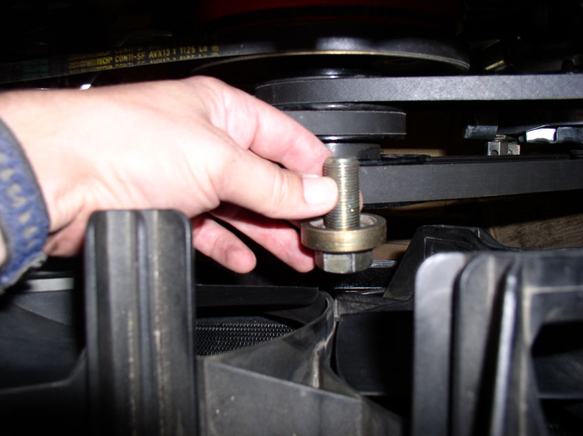
I used an M6 (10mm bolt) the same size bolt that is used to secure the water
pump to the block (I had spares) as the counterforce for the puller. Insert the
bolt part way into the threads as shown and install the puller.
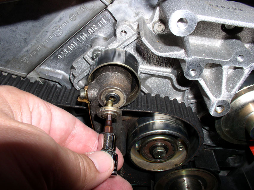
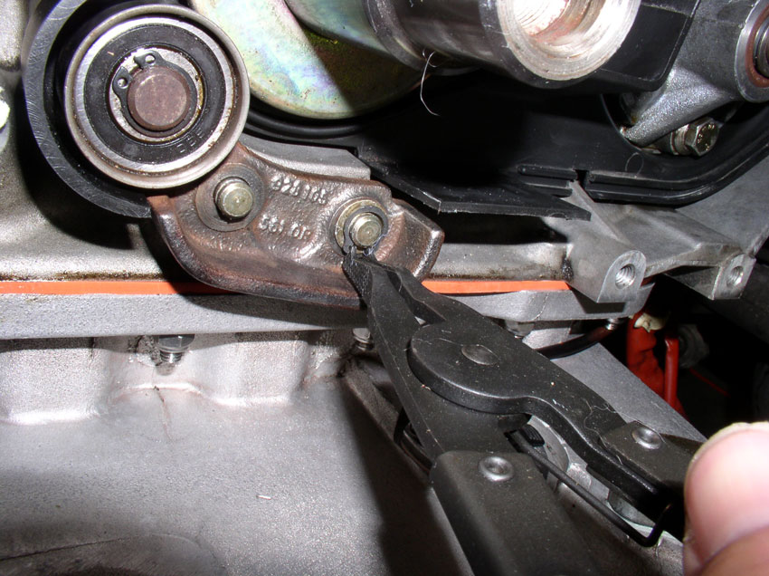
Slowly pull the idler pulley off the spindle....
If you need more of the 10mm bolt exposed, simply unscrew it some more and
continue pulling with the puller.
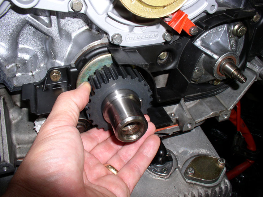
Eventually, the idler pulley comes off the spindle.
Set aside the tensioner pulley assembly. We'll work on it later to replace the
pulley and bushings.
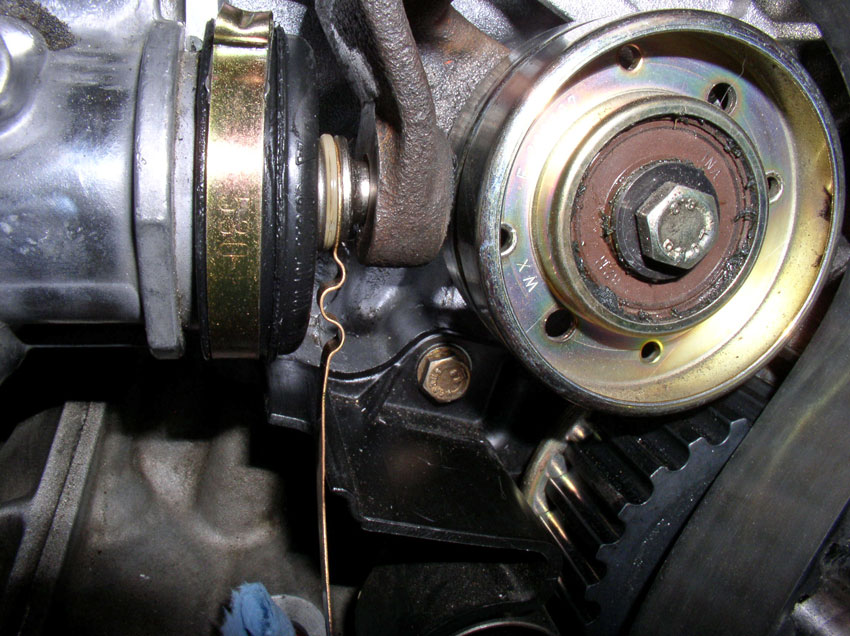
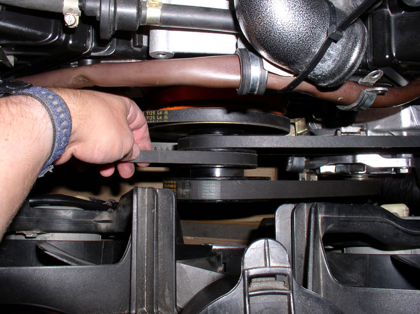
Next, remove the outer timing belt guide from the crank timing belt gear....
....and slide the timing belt out from the crank gear as shown.
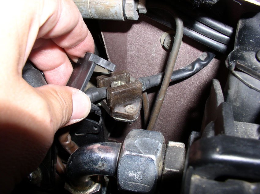
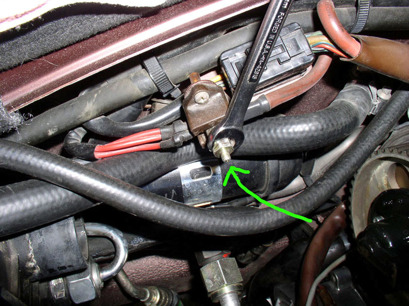
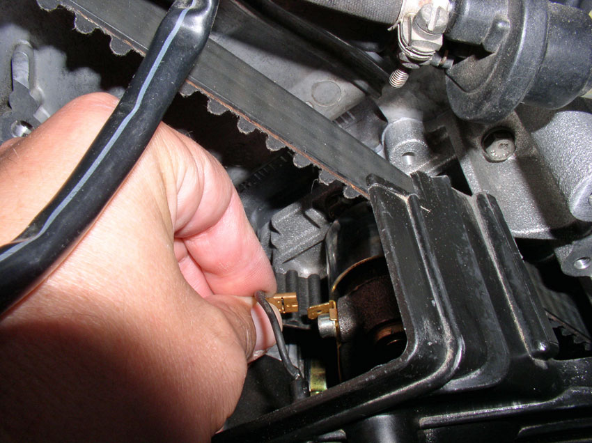
Now the timing belt is ready to come off but we need to disconnect a couple of
wiring harnesses in order to remove the belt. We'll start with the small wring
harness that runs along the driver's side of the firewall behind the power
steering reservoir mounting bracket. You can trace this harness to its
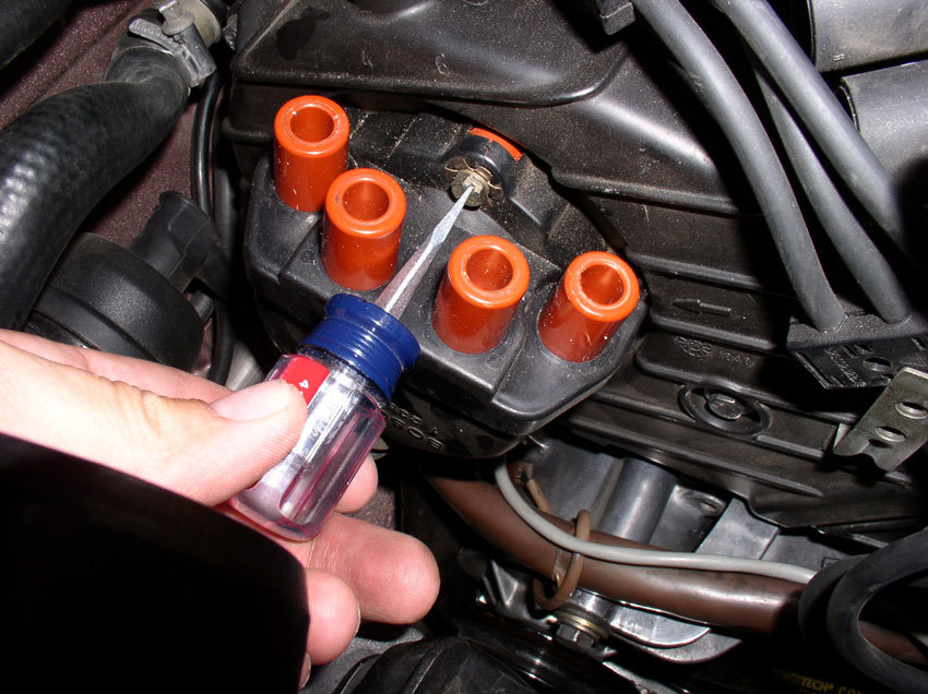
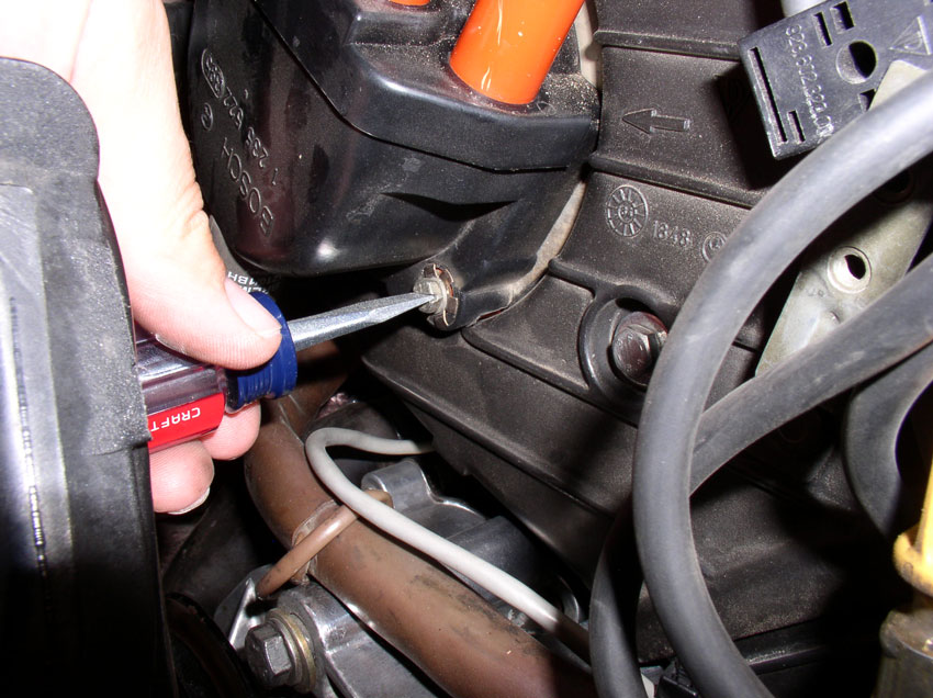
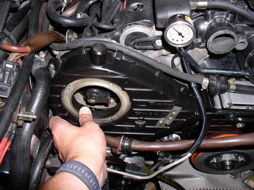
connection point at the small box pictured below. Pop the protective top off to
expose the phillips screw
underneath as shown.
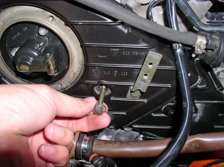
Using a phillips
screwdriver, loosen and remove the phillips screw
securing the wiring harness as shown.
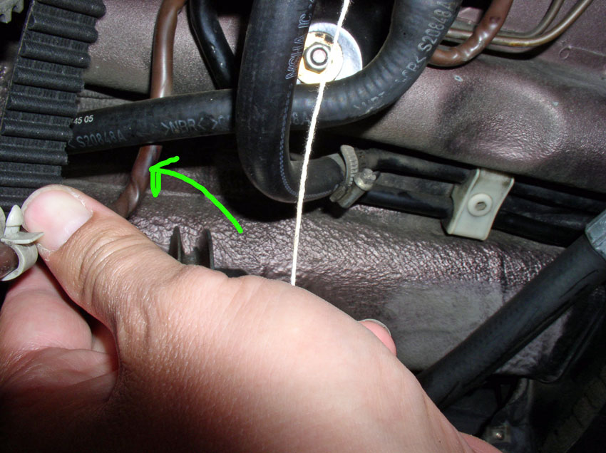
Back out the harness from behind the power steering reservoir bracket as shown.
Continue backing out the harness from behind the power steering hoses as shown.
Now, the small harness should be free.
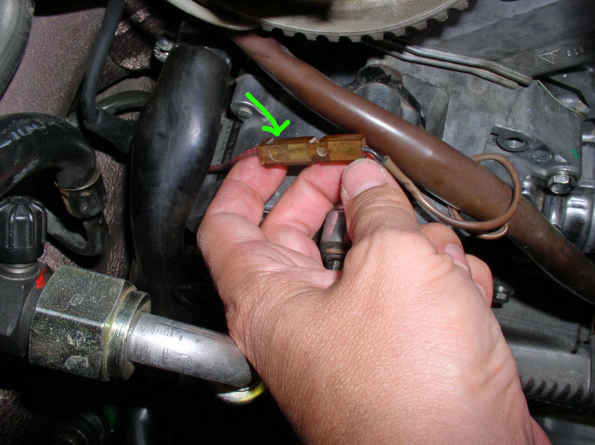
Next, we need to do the same for larger wiring harness pictured below. First,
disconnect the power wire to the A/C compressor (the red wire that comes out of
the brown square plastic connector pictured below. Pull the red wire out from
the connector.
Remove the harness clamp that is attached to the engine lift hook at the
passenger front side of the engine as pictured below. The clamp is secured with
a 10mm bolt. Loosen and remove the 10mm bolt. Remove the harness from the
clamp.
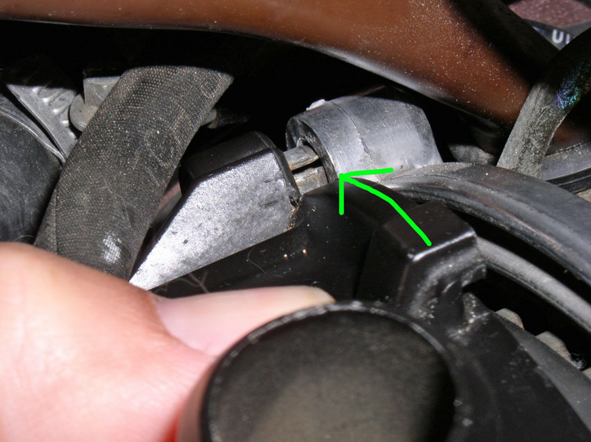
Loosen and remove the 11mm charge post bolt as pictured below. Pull the harness
wire out and replace the bolt in the connector.
Lift up and remove the upper half of the 14-pin harness connector as shown
below.
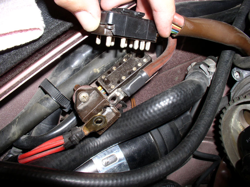
Back feed the harness back behind the cam cover back plate as shown.
Pull the harness all they way out from behind the cam as shown. Now the large
harness is free and you can remove the timing belt.
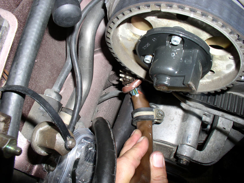
Once the timing belt is free, you can do the victory dance!
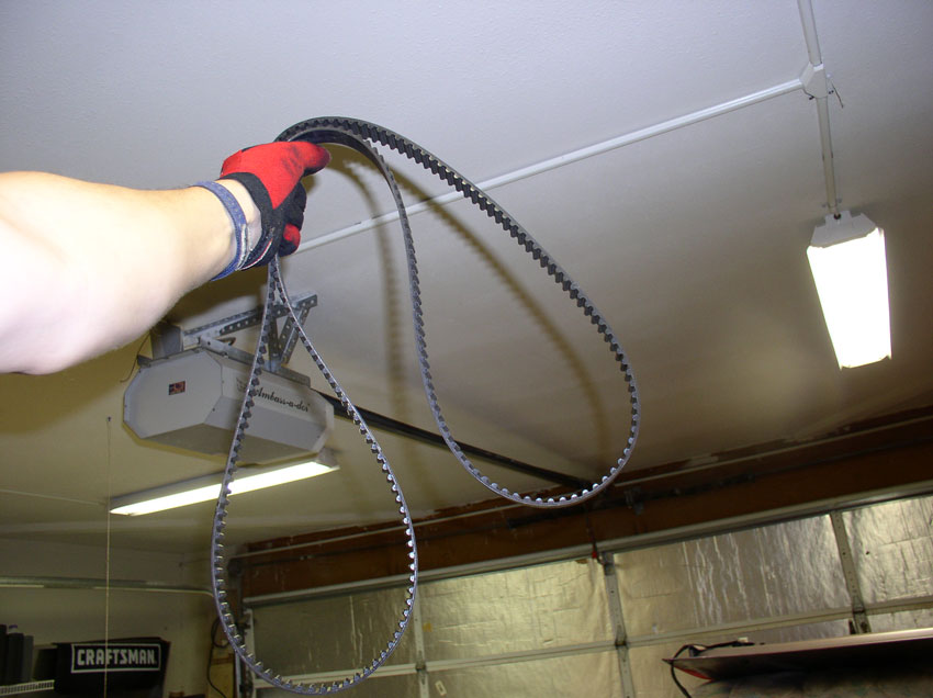
Removing the water pump is next.
CH09 Removing Water Pump
The water pump is secured with 13 10mm bolts. At this point, you
can begin removing all the bolts.
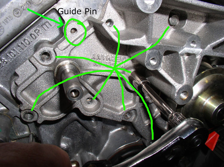
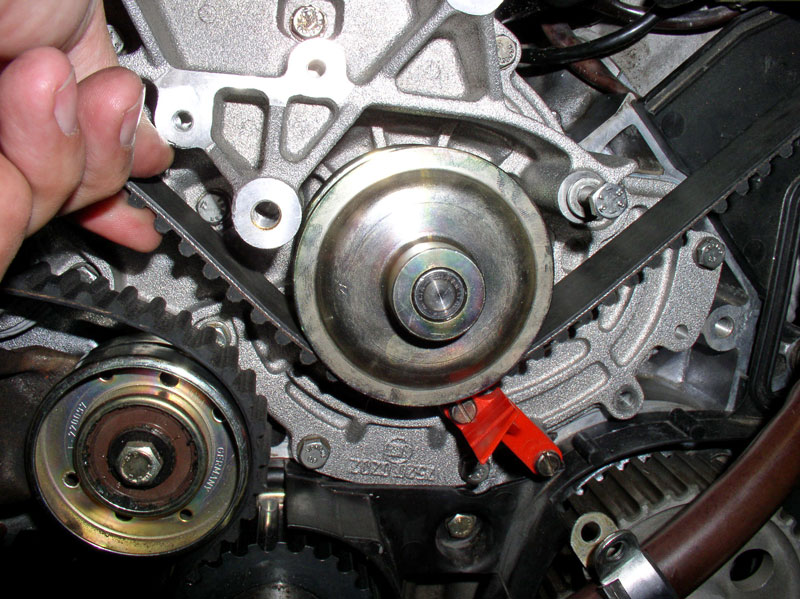
There are 8 bolts to the left of the pulley as depicted in the below picture.
The remaining 5 bolts are to the right of the pulley. You will also notice that
5 of the bolts are shorter than the others. These 5 bolts are matched with the
holes that are recessed in the water pump housing - there are 5 of them. Finally,
notice the guide pins. There is one on each side of the water pump. Depicted in
the picture below is the guide pin on the left side of the water pump. There is
another on the right side of the water pump. These are great for locating the
water pump properly when installing. However, they can be bent or broken off if
the water pump is forced off at an angle.
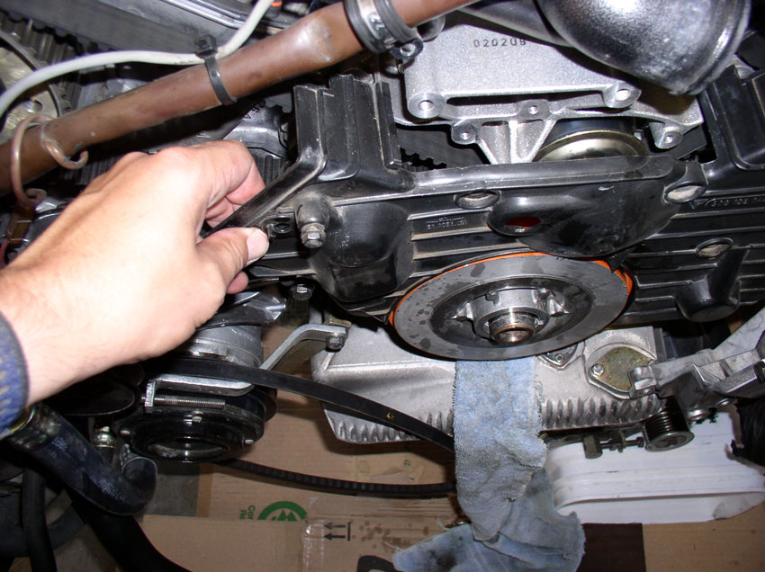
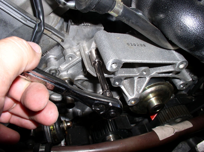
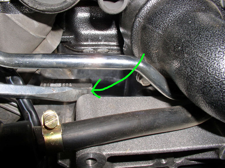
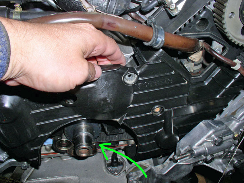
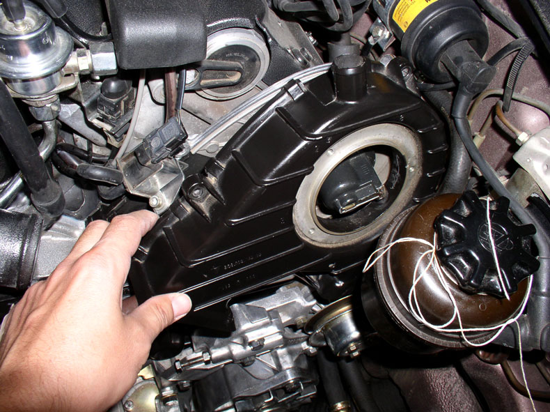
When all the bolts have been removed, you can pull the water pump off. It will
probably be stuck on so you may need to pry it off. The method that works well
for me is to gently pry the pump off by inserting a large flat blade
screwdriver between the engine block (where the engine block number is stamped)
and the water pump housing. Do not pry much, just enough to break the bond and
allow you to "walk" the pump off the guide pins. Pull on one side
then the other then the other side and so on until the pump comes off.
Once the pump is off, set it aside.
Continued….
CH10 Removing Oil Pump Gear and
Rear Timing Belt Cover
If you would like to replace a leaking o-ring or seal on the oil
pump, this next section should help. However, if not, you can skip to Chapter
13 to resume with the regularly scheduled program of timing belt and water
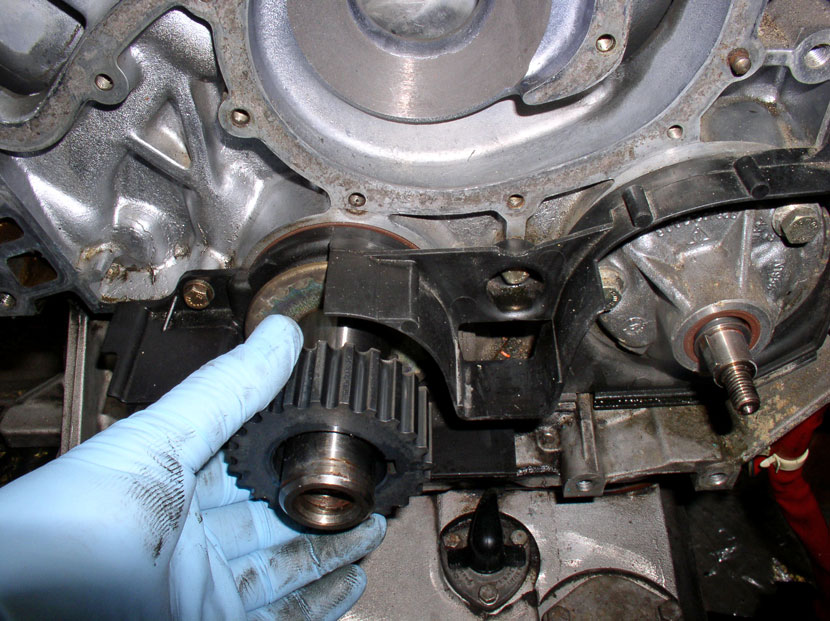
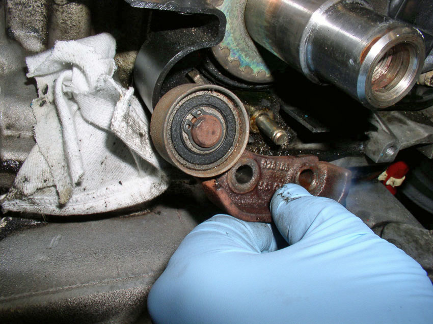
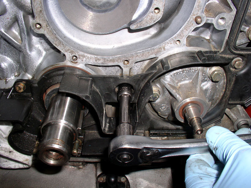
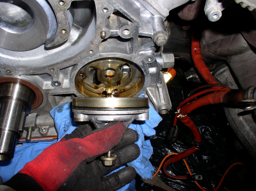
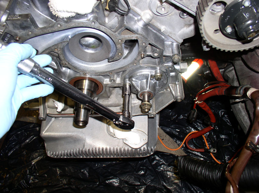
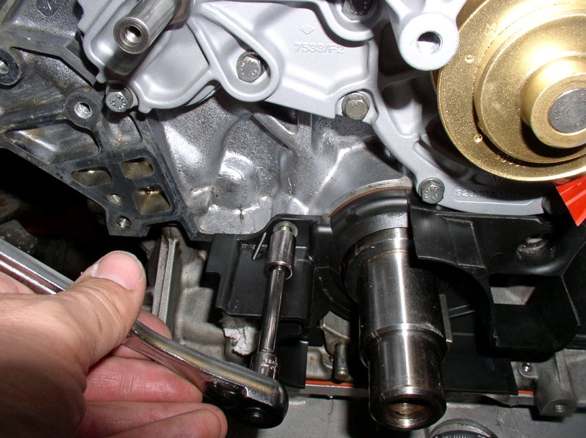
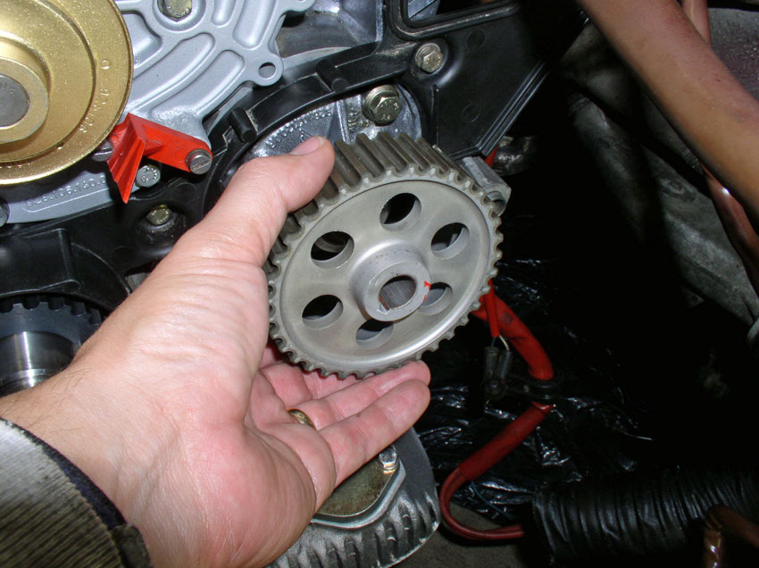
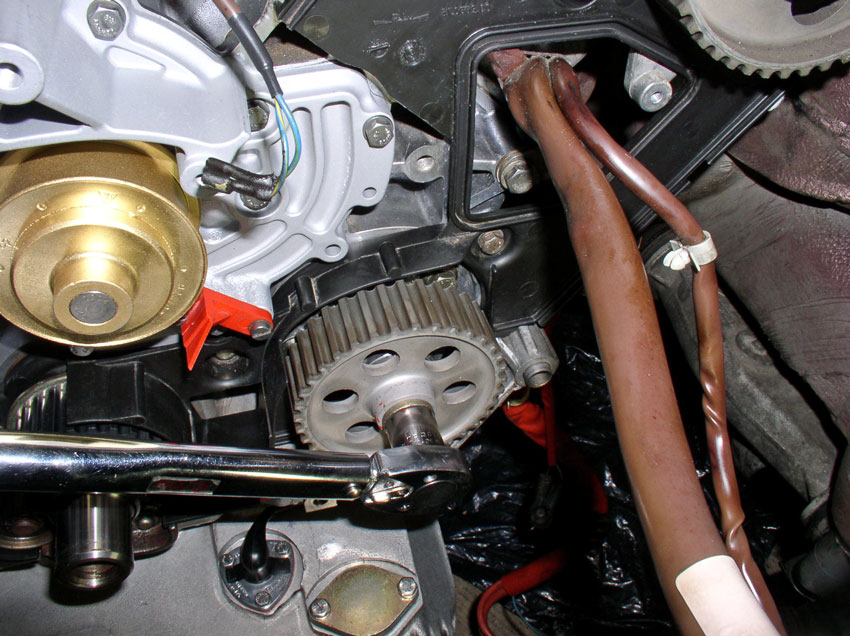
pump. First, we remove the oil pump gear. It is secured with a 17mm nut. You
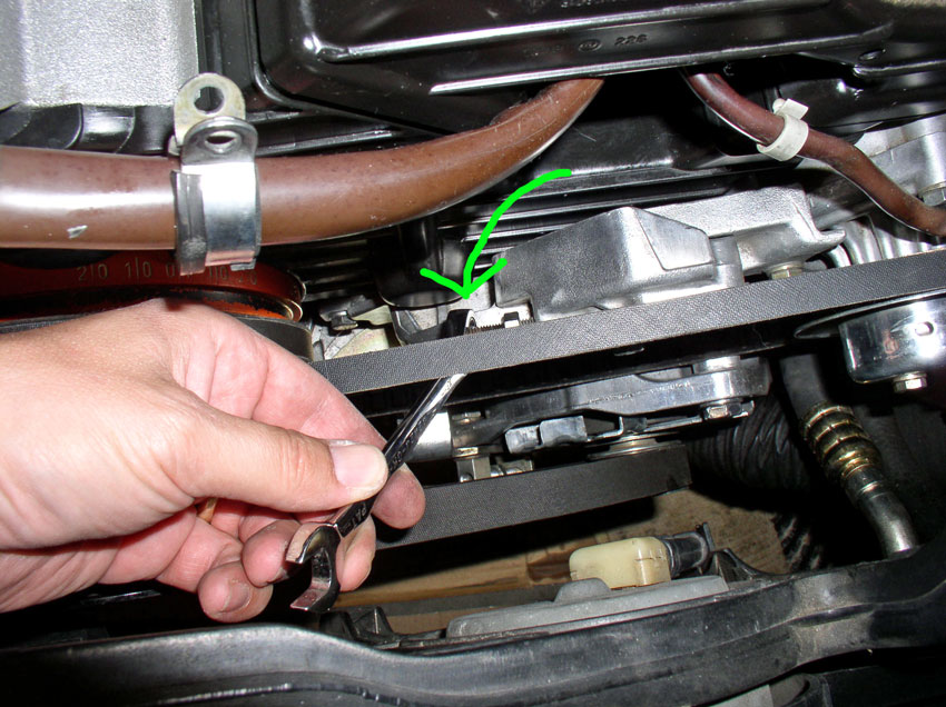
can counter hold the gear using a large flat blade screwdriver or pry bar by
inserting the screwdriver in one of the gear holes and catching one of the
casting ridges behind the gear as shown below.
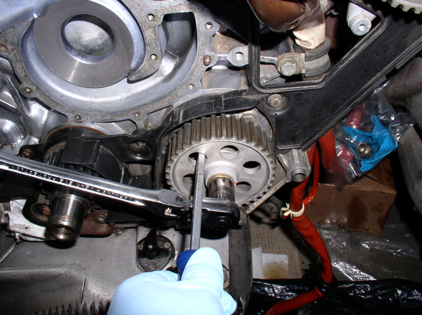
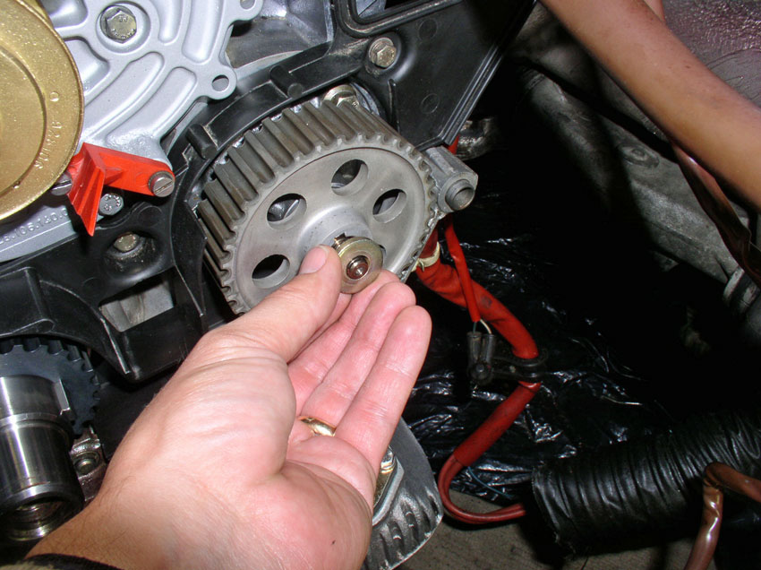
Once the gear nut is loosened, remove the nut and washer.
You can try to pull off the gear by hand but most likely it will be stuck. Mine
was so I used a 2-Jaw puller and it came right off.
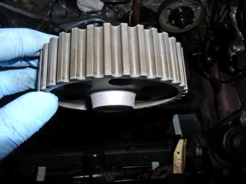
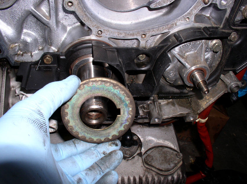
Once the gear is off, inspect the coating on the gear. The coating can wear off
and expose the soft metal below. If the gear looks like shiny metal, the
coating has worn off and the gear should be replaced. If the gear looks like
the one pictured below, the coating is still intact and can be put back into
service. This particular gear had about 34K miles on it.
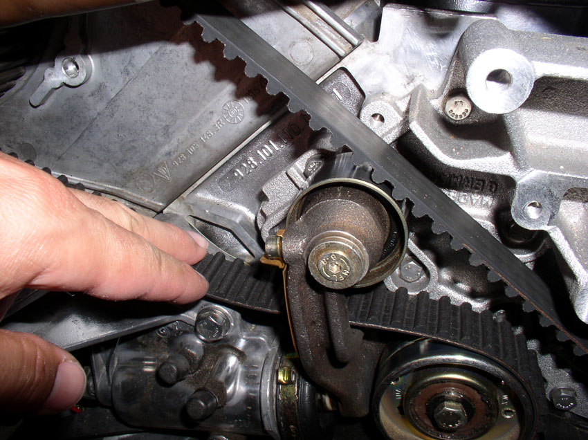
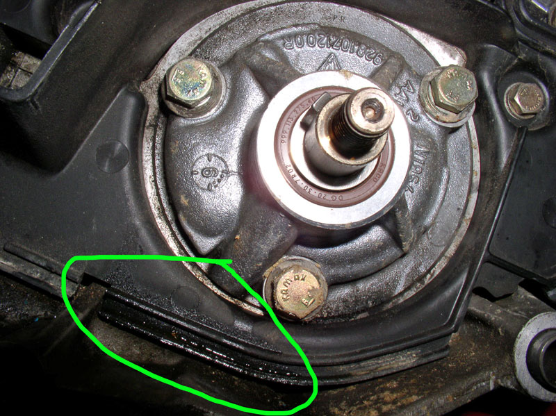
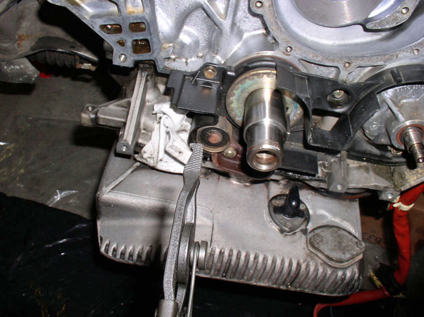
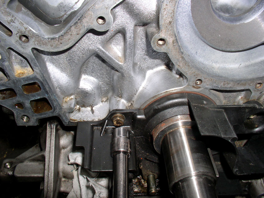
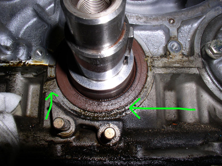
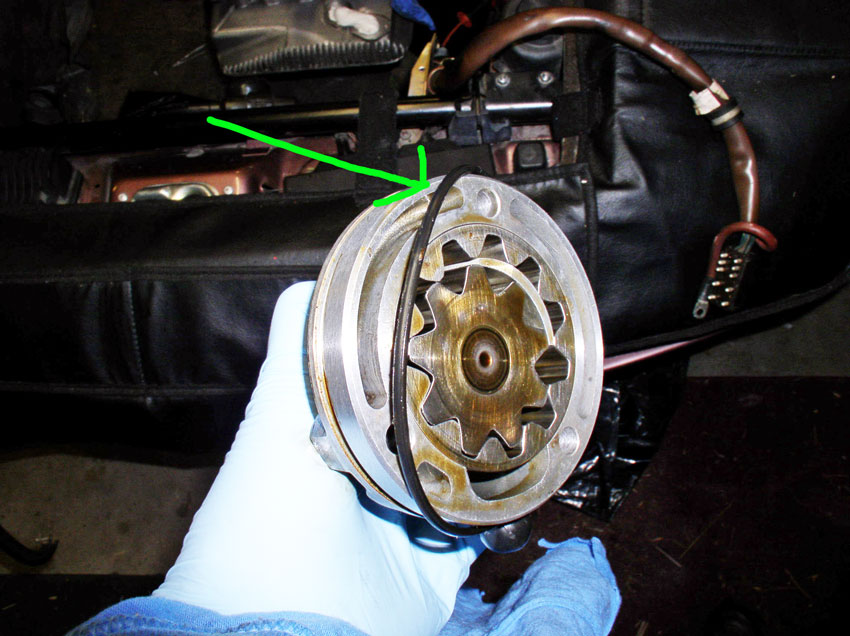
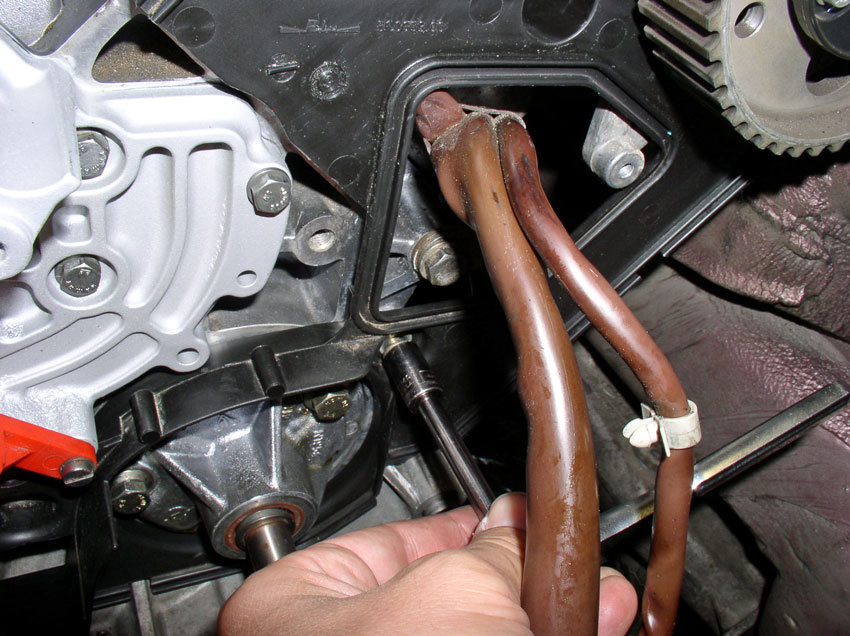
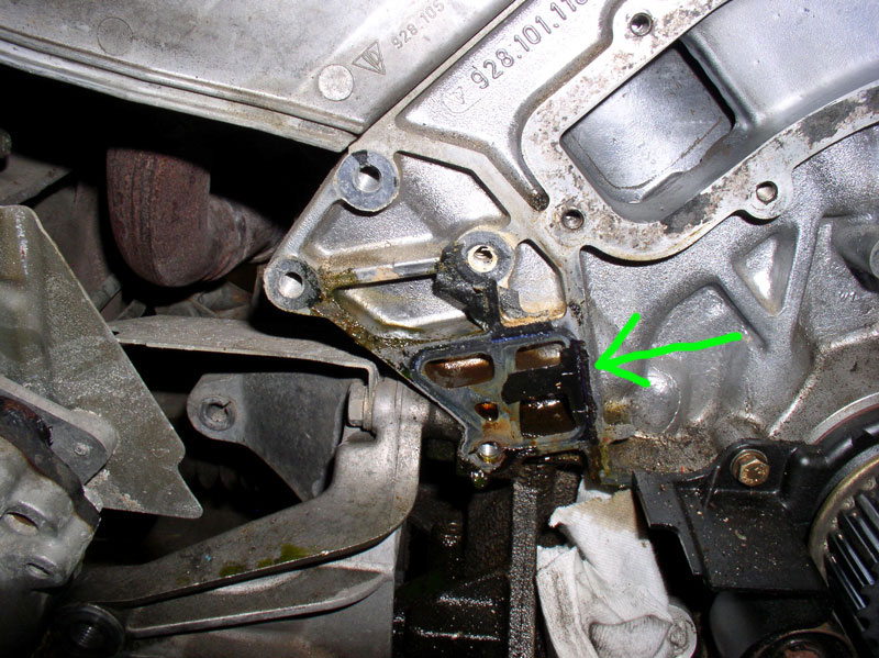
Once the gear is off, you can inspect the seals and mating surfaces to look for
leaks. You can see here with mine that there is some weeping or light leaking
below the oil pump. The brown seal around the pump spindle above the circled
area appears clean with no leaks. The lower leak is probably due to a worn out
O-ring on the pump housing. It appears the oil pump can be removed without
removing the rear plastic cam cover shown in the background. However, since I
wanted to clean it all up, I removed the cam cover as illustrated in the
following steps.
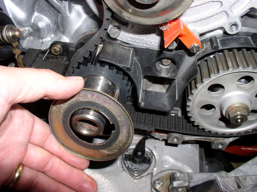
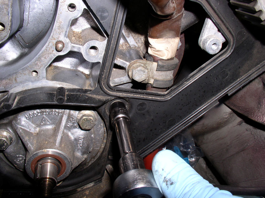
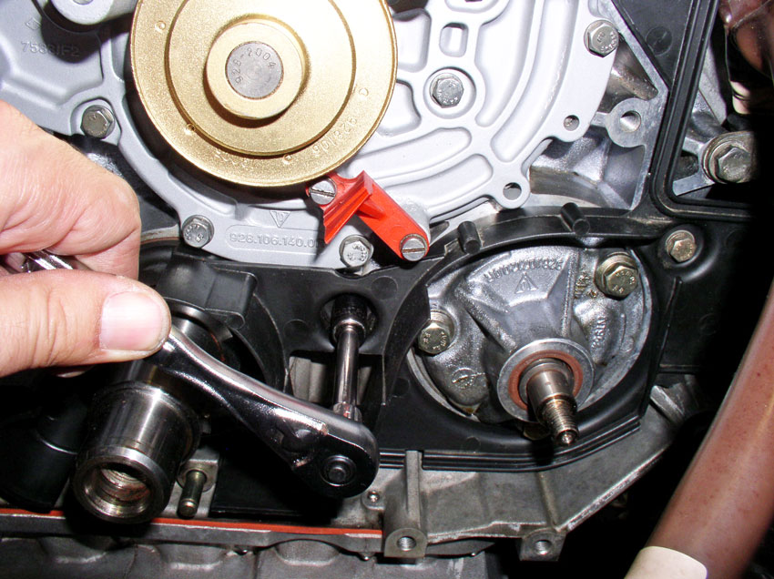
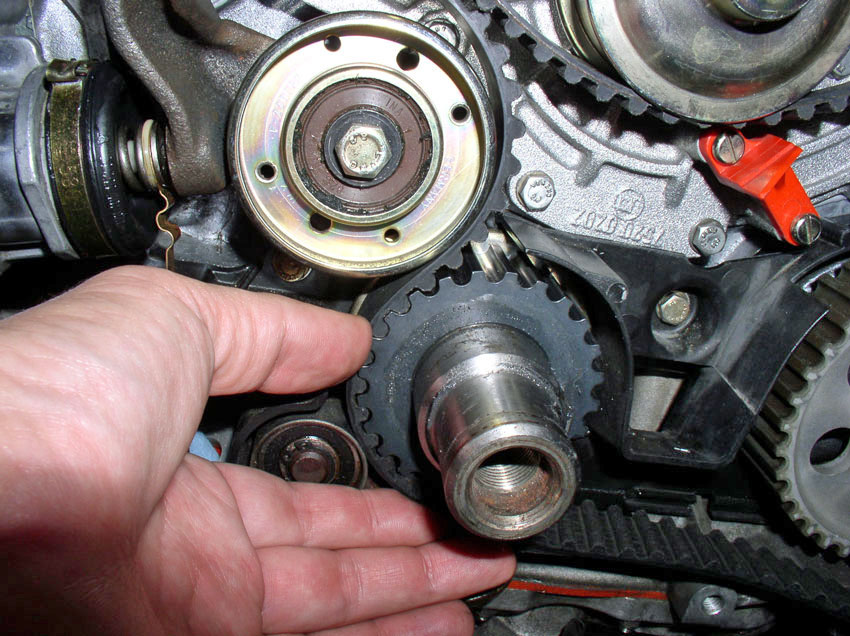
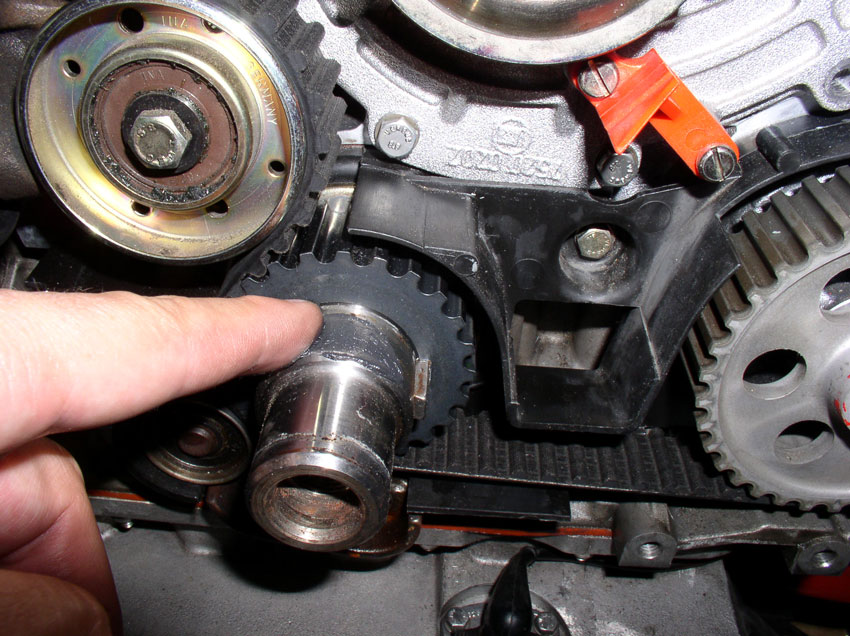
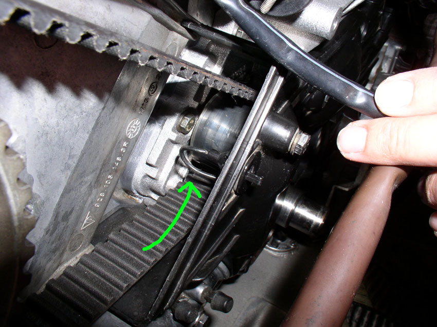
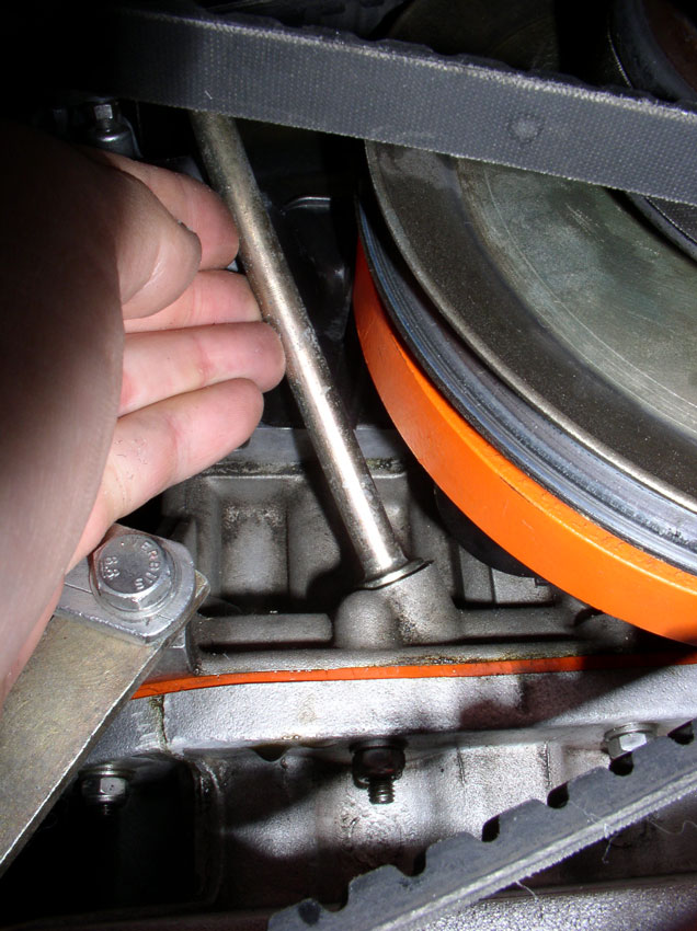
First, remove the crank timing belt gear from the crank shaft. Sometimes the
gear will not slide off because the "key" is angled or wedged in at
an angle. If the gear does not slide over the key, you can gently tap the key
to align it as shown below.
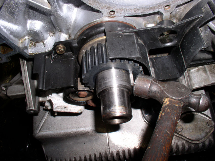
The gear should slide off at this point.
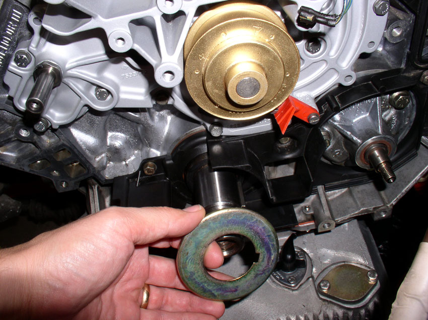
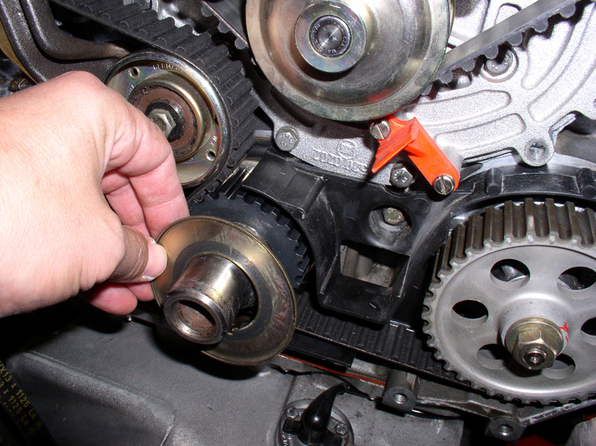
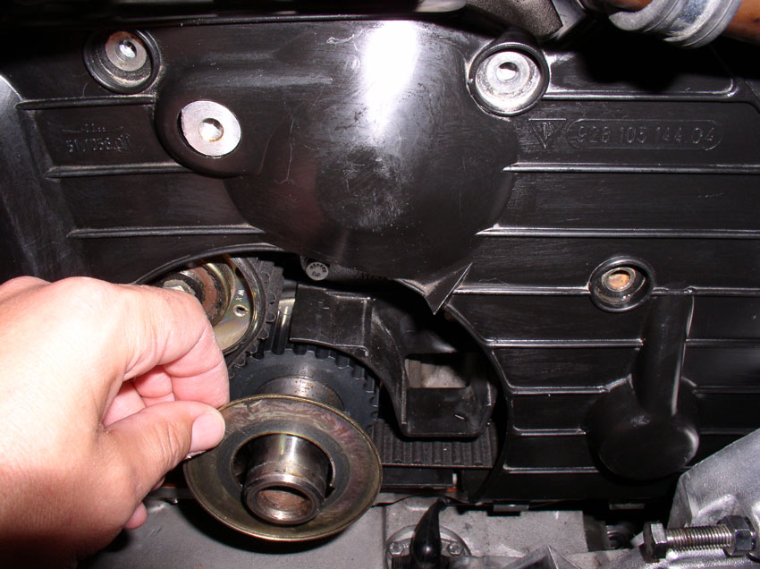
Next, remove the pulley below the crank shaft. You will need a small pair of circlip pliers.
Remove both of the circlips on the pulley assembly as
shown.
Remove both of the washers behind the circlips as
shown.
Remove the pulley assembly. As you can see from the pic,
the assembly never gets used or comes in contact with the belt. I'm not sure
why it's still present.
Remove the inner timing belt guide from the crank shaft.
The rear timing belt cover is secured with 5 bolts. First, remove the 5mm allen head bolt that resides
behind the metal cam cover backplate as shown. You
will notice it also secures a grounding wire between the engine and the fender
at the coil mounting bracket (see pic). Remove the
bolt.
There is another 5mm allen
head bolt on the other side of the cam shaft between the head and the metal cam
cover backplate. Remove the bolt.
Next, remove the center 10mm bolt as pictured.
Remove the 10mm bolt to the right.....
....and the 10mm bolt to the left on the cover.
At this point, you can remove the back cover. You will have to feed the wiring
harnesses through just as you did with the timing belt.
Now you can clean the area before removing the pump which is detailed next.
CH11 Removing Oil Pump and
Replacing O-Rings
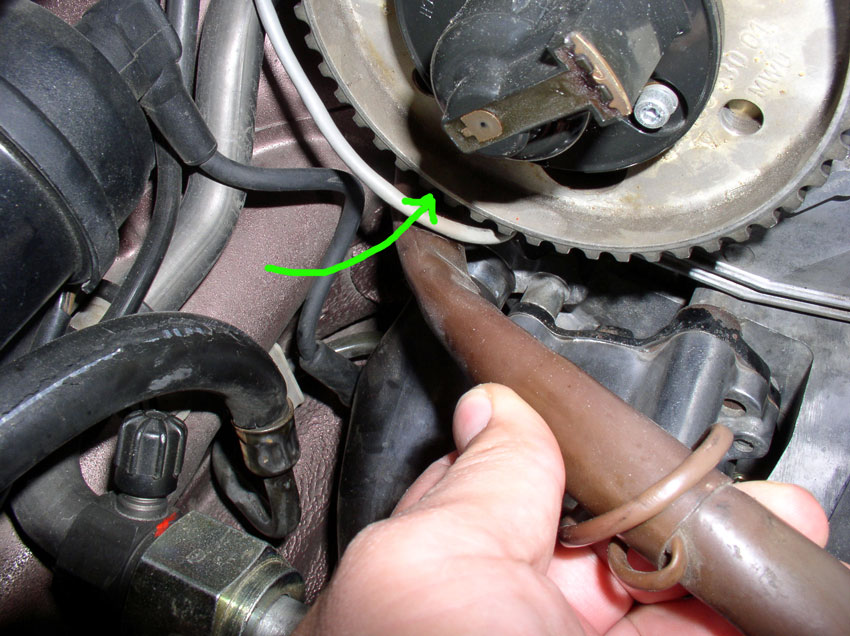
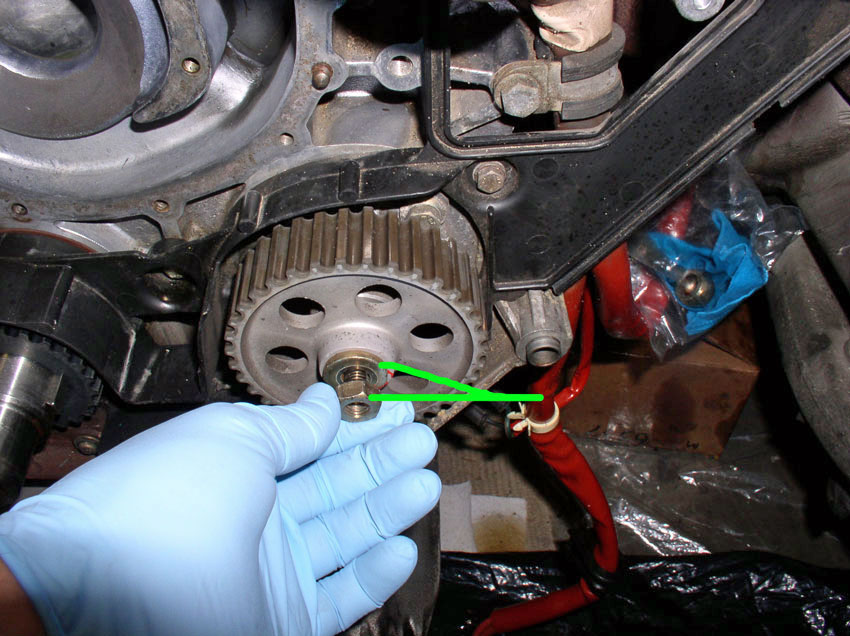
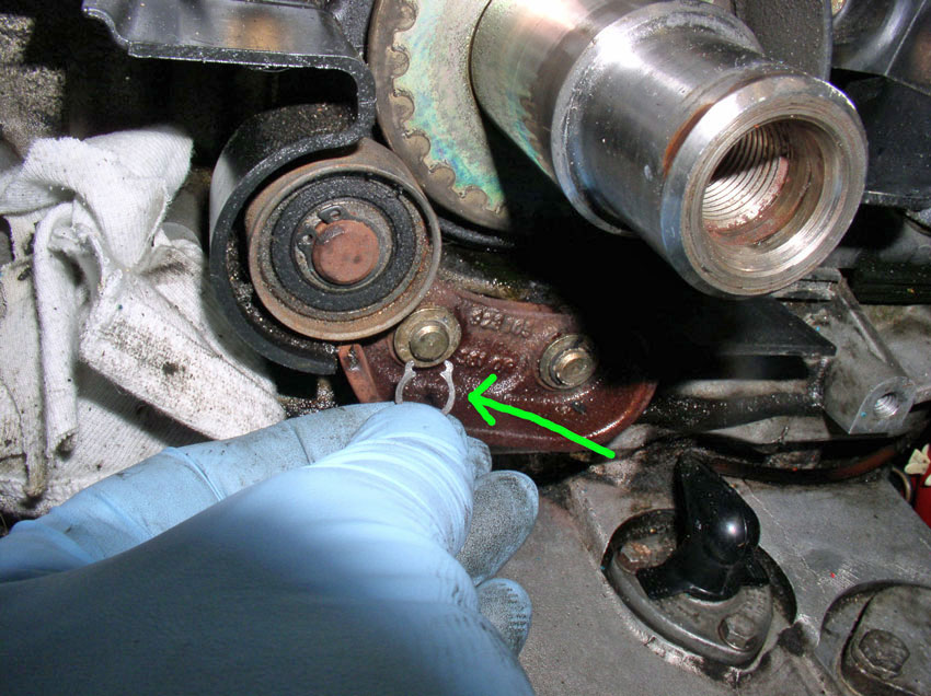
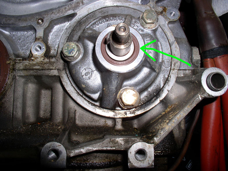
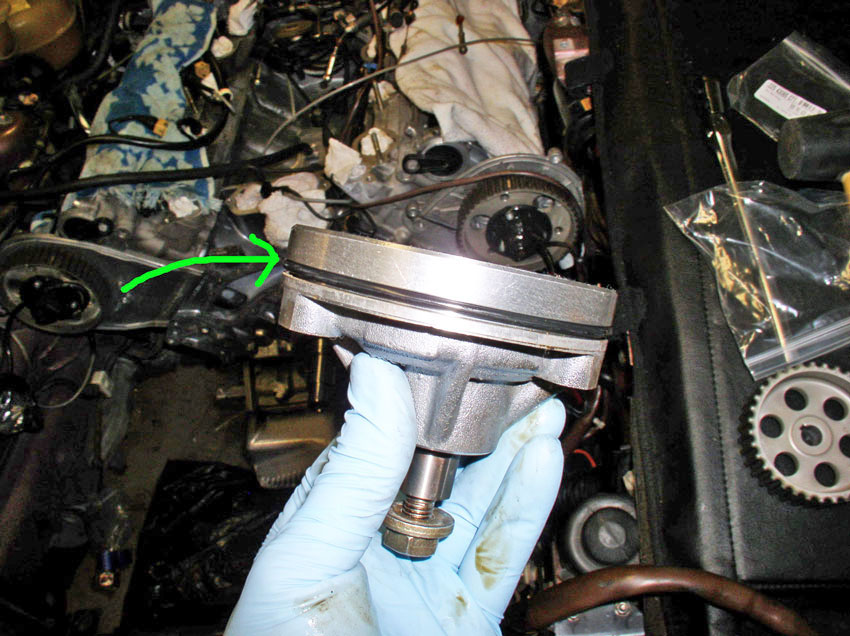
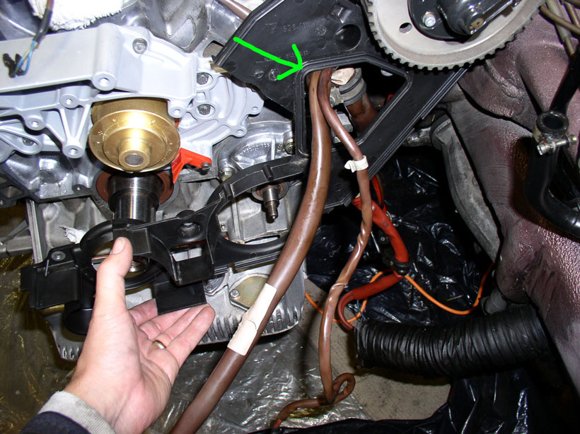
The oil pump has a seal on the spindle as indicated by the green
arrow in the pic below. This seal was in very good
shape so I left it alone. However, if you wanted to replace it, when the pump
is removed, you can remove the gears and spindle and can easily replace the
seal with a new one. That procedure is not covered here.
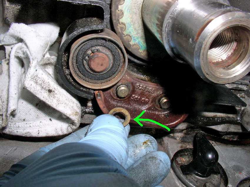
Also, you can inspect the crank shaft front seal for leaks. It appears from
this pic below, my seal may be weeping (slight leak).
I decided to leave it alone and monitor it for leaking. If
you were going to replace seal. Now would be the time to do it. You can
see by the green arrow to the left, there is a canal cut into the engine block
that will give you access to pry the old seal out. Once the old seal is out,
you can press the new one in. However, that procedure is not covered here. I
will replace the seal the next time I'm in there.
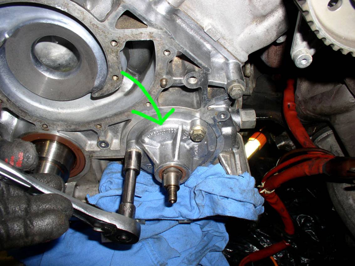
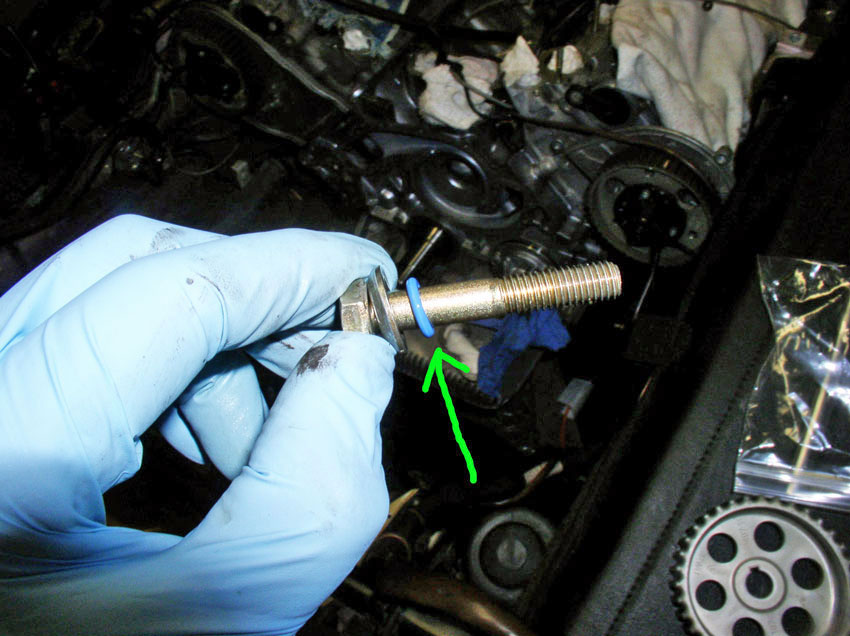
To remove the oil pump, remove the three 13mm bolts that secure the pump to the
engine block. Each bolt has an umbrella washer and an o-ring. We'll be
replacing the o-rings later.
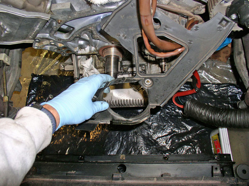
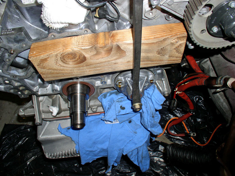
Once you get the bolts out, you will need to pry or pull the pump out. The
method that worked well for me was to use a short section of 2X4 and a long pry
bar. Put the gear washer and bolt back on the spindle as shown below. Place the
2X4 against the block and use the pry bar to lever against the 2X4 and the
washer and bolt to carefully pry the pump out (see below).
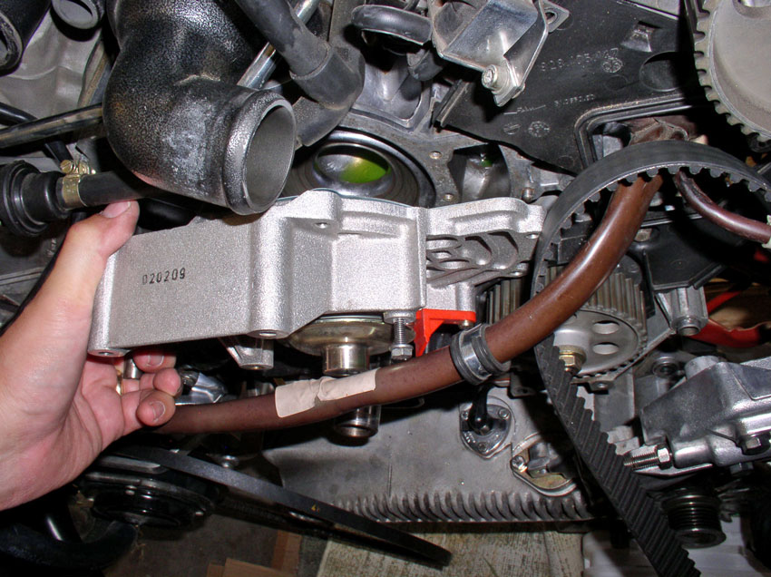
Make note of the oil pump orientation. For example, mine had the part number at
the top. Remove the pump as shown.
Use a small screwdriver or pick tool to remove the old oil pump O-Ring as
shown.
Install the new O-Ring and coat with some motor oil to help it slide back in on
install.
Remove the old O-Rings from the 3 mounting bolts and install the new O-rings
one on each bolt.
Place the Oil Pump back into the block in the same orientation as it came out
and re-install the three 13mm mounting bolts as shown. The bolts are torqued down in a two step process. First pass, torque down
to 11 Ftlbs, on the second pass, torque to 14 Ftlbs.
CH12 Installing Rear Timing
Belt Cover and Oil Pump Gear
Feed the wiring harnesses through the access hole in the timing
belt rear cover and position the cover into place as shown.
Install the 5mm allen head
Bolt as shown. Ensure the grounding wire is installed underneath as pictured.
Install the 2nd 5mm allen
head bolt as shown.
Install the first of 3 10mm bolts as shown below.
Install the second mounting bolt, 10mm.
And the final 10mm mounting bolt as shown.
Next, install the rear timing belt guide onto the crank shaft as shown.
Followed by the pulley assembly as shown. Mount it on
the two pins.
Install the washers.
Install the circlips as shown. If the clips are
stretched out, you can carefully clamp them back into shape with a pair of
pliers.
Install the timing belt gear onto the crank shaft.
Install the oil pump gear on its shaft as shown.
Install the washer and the gear nut next.
While counterholding the gear, tighten the gear nut
to 30 Ftlbs.
CH13 Repairing/Replacing
Tensioner Pulley and Tensioner Bushings
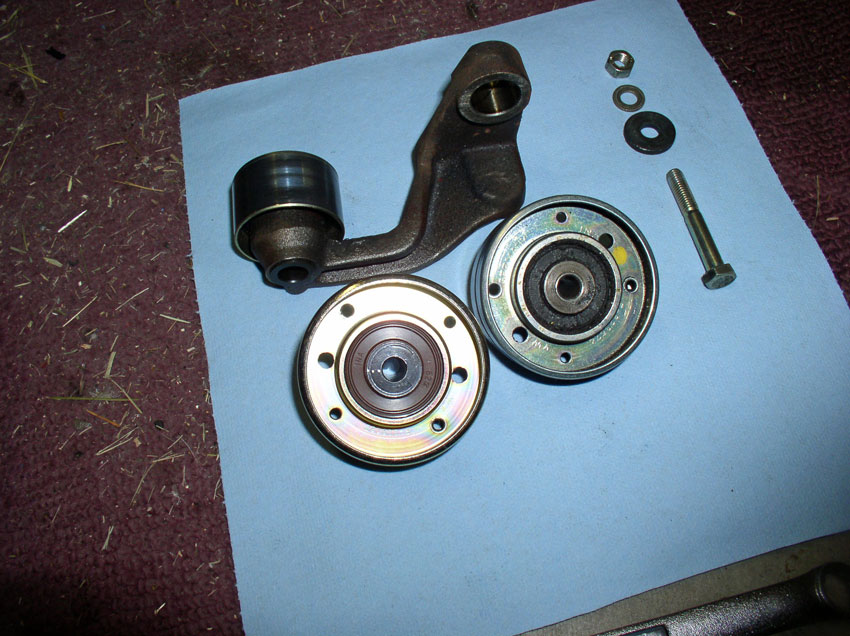
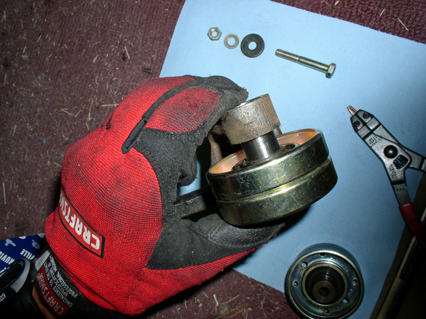
Next, we'll replace the tensioner pulley and bushings.
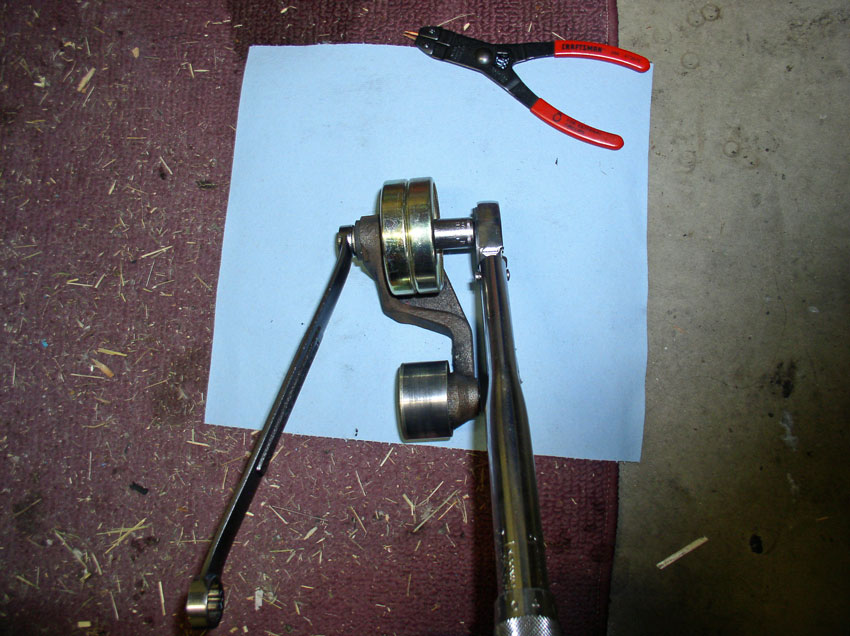
The pulley is mounted to the arm with a 13mm bolt and nut. Counter hold the
13mm nut while loosening the 13mm bolt. Remove the nut and bolt from the pulley
and arm assembly
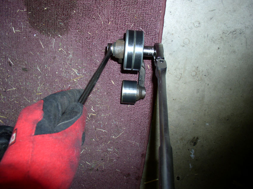
Here's a picture of the disassembled bolt and washers
and pulleys (old an new).
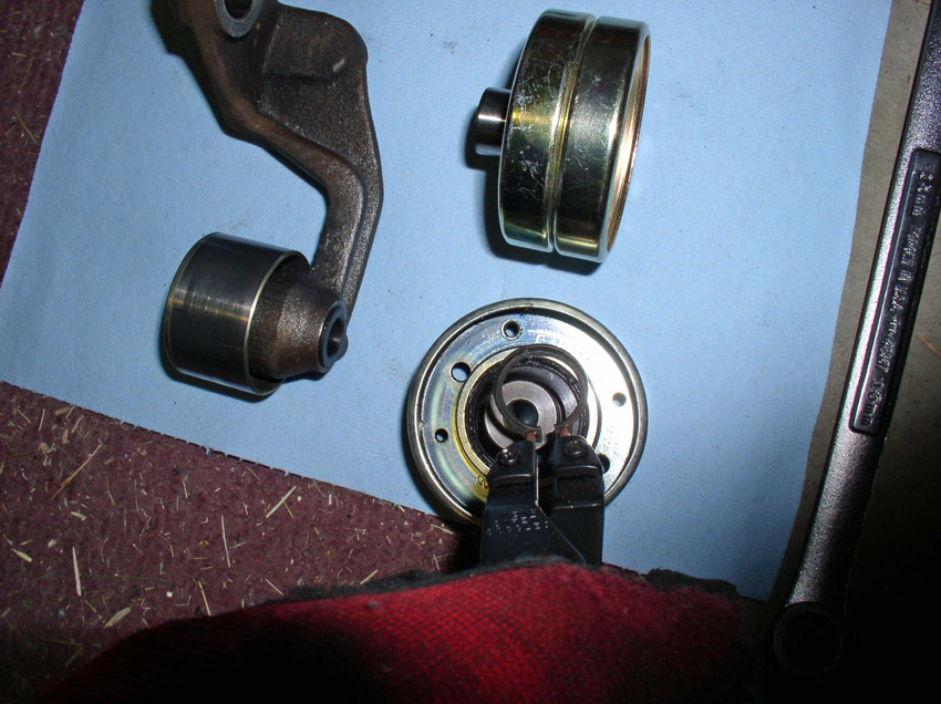
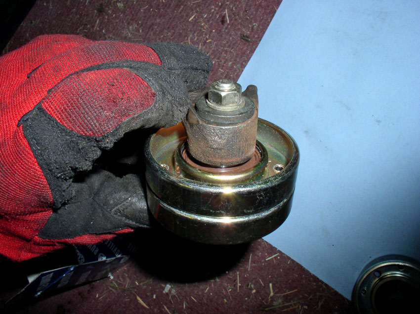
You will need to transfer the large circlip from the
old pulley to the new pulley. Use a pair of circlip
pliers to remove the clip from the old pulley.
And install in the groove on the new pulley.
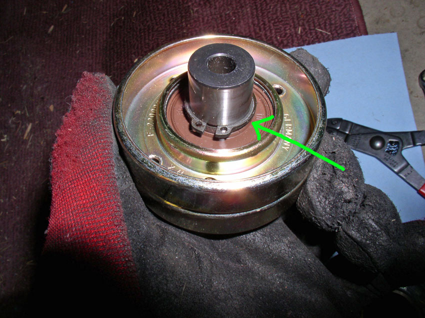
Ensure the circlip is fully seated in the groove as
pictured.
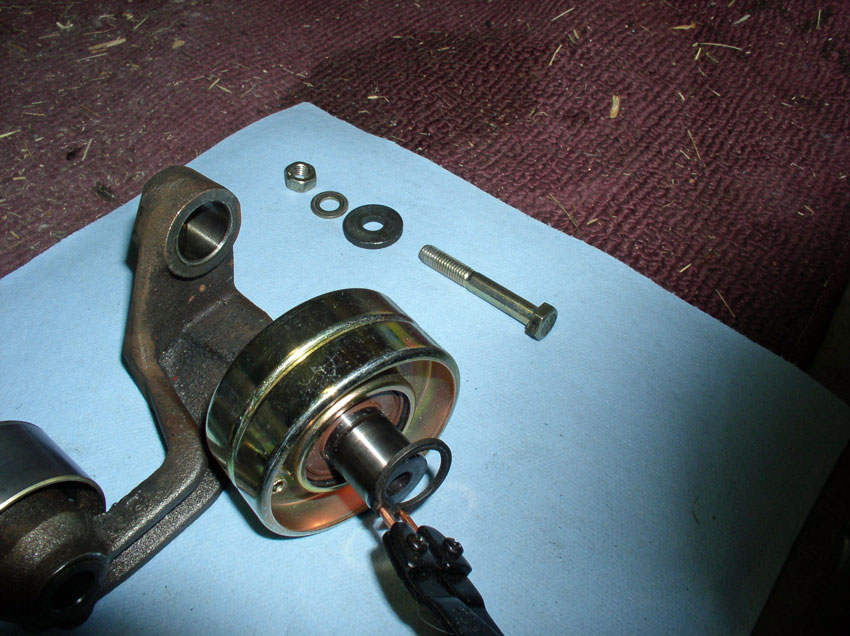
Install the new pulley into the arm as shown with the circlip
facing/contacting the tensioner arm.
Install the bolt from the front of the pulley and install the thick washer
first followed by the 2nd washer and finally the nut as pictured.
Counter hold the nut and torque the bolt to 15 Ftlbs.
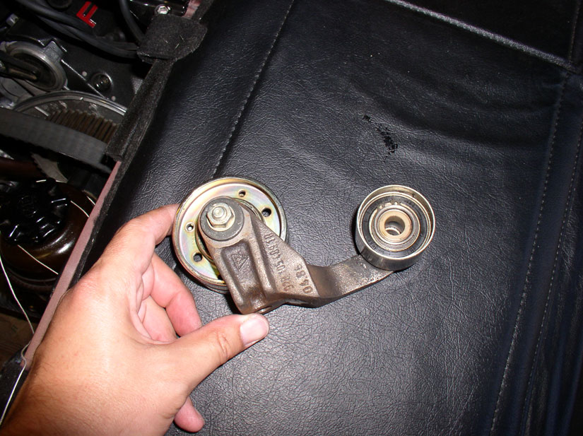
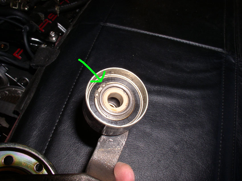
The idler pulley can also be replaced at this time. Mine, however, was still in
great shape so I did not replace it. If you are going to replace it, you have
to remove this circlip as shown in the picture below.
Then separate the pulley from the arm and install the new pulley. The idler
pulley helps keep the timing belt from flopping and coming in contact with the
pulley mounting hardware since the most slack in the
timing belt is in the area of the tensioner pulley. I don't believe the idler
pulley is replaced regularly.
The bushings should be replaced next. To get the old bushings out, I used a
pick tool and grabbed the inside edge and pulled up.
It moved a little at a time but eventually came out. There is a bushing on each
side of the pulley. Remove the 2nd bushing as well.
Place the new bushing into the mounting hole.
The bushings are usually a tight fit so you may need to use a "C"
clamp to press them in evenly and flush with the mounting bracket. After both
bushings are installed the tensioner pulley assembly is ready for installation
(later in Chapter 17)
citibank credit card home pageCH14 Removing and Repairing
Timing Belt Tensioner
The next sequence of pictures may seem out of order since the
timing belt and tensioner pulley are still on the engine but you can ignore
those. I had to use an older set of pictures to capture the rebuild process. To
remove the timing belt tensioner, you will need to remove the air pump from the
tensioner bracket. Loosen and remove the 13mm pivot bolt on the air pump as
shown.
Work the air pump back and forth while pushing down and work it out of the
bracket. When it comes out, set it aside down below out of the way.
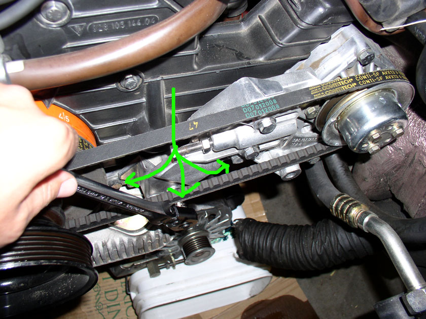
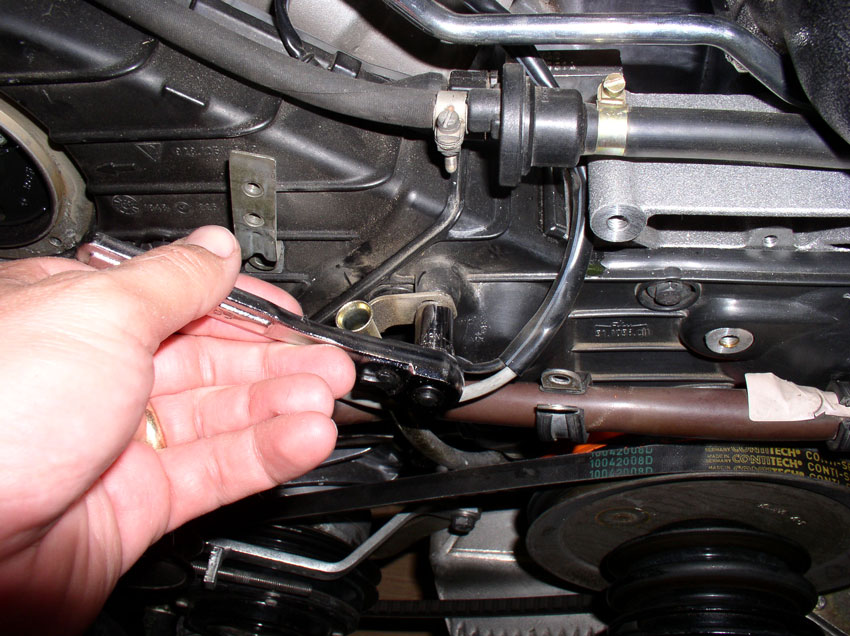
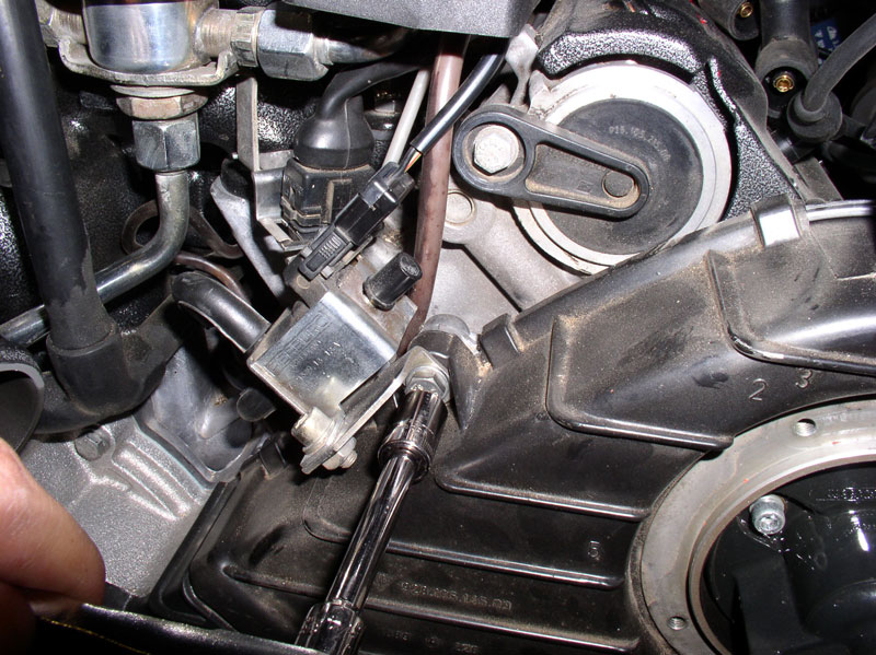
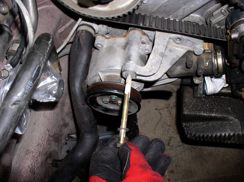
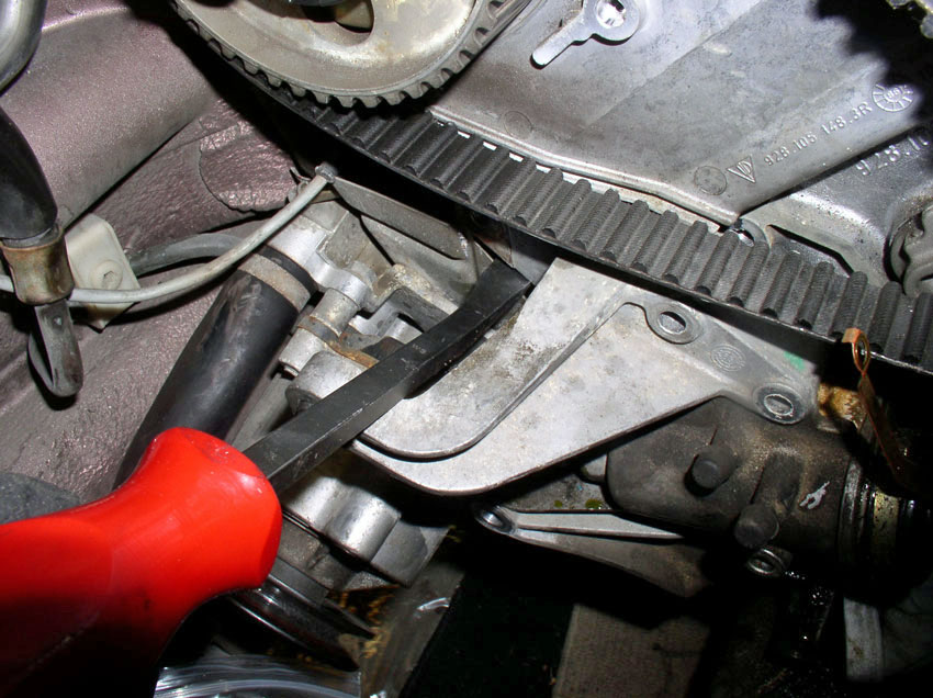
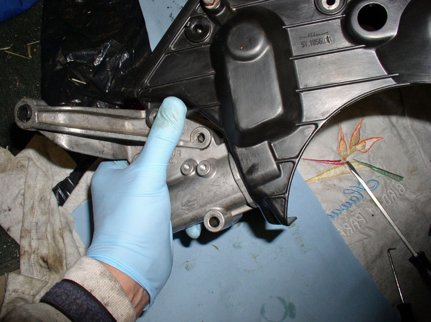
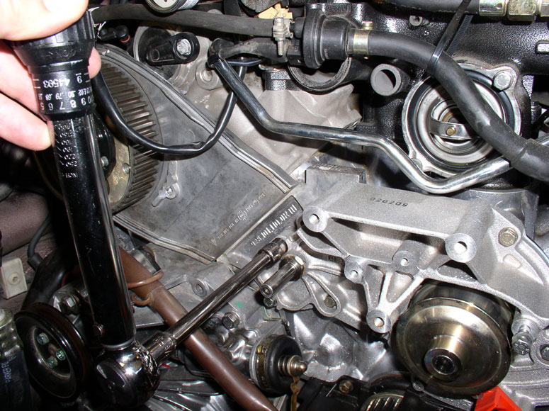
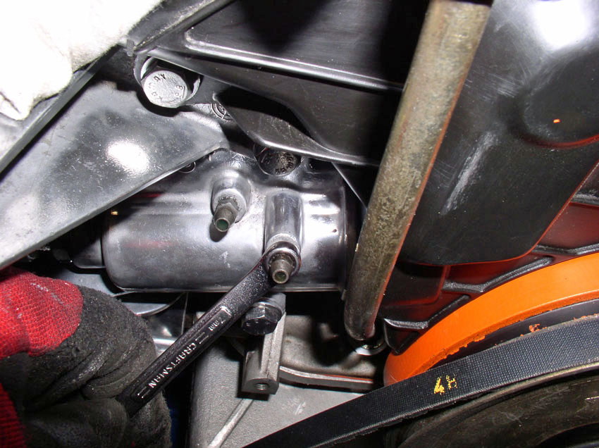
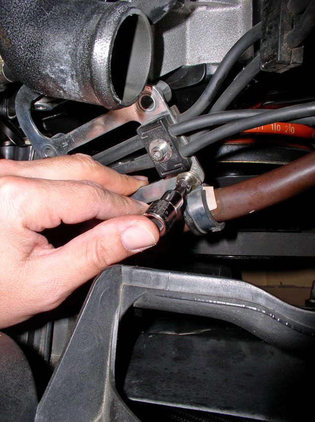
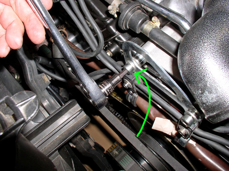
The tensioner is attached to the block with three 13mm bolts. Two are easily
visible but the third is to the left and hard to see under the bracket arm.
Loosen and remove the mounting bolts.
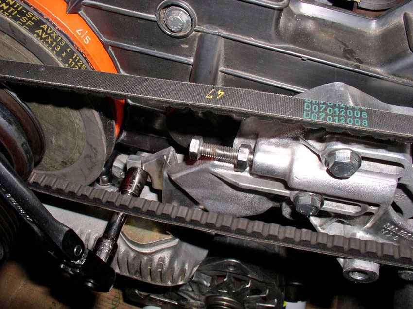
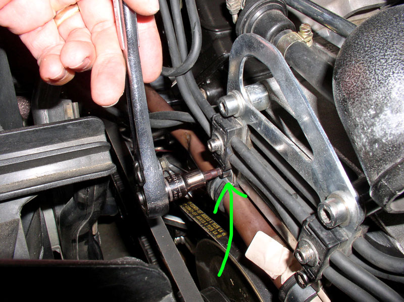
Here's a shot at the 3rd bolt located under the bracket arm.
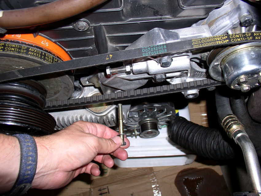
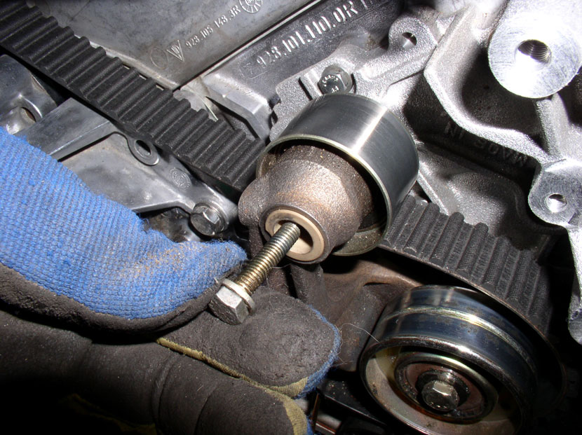
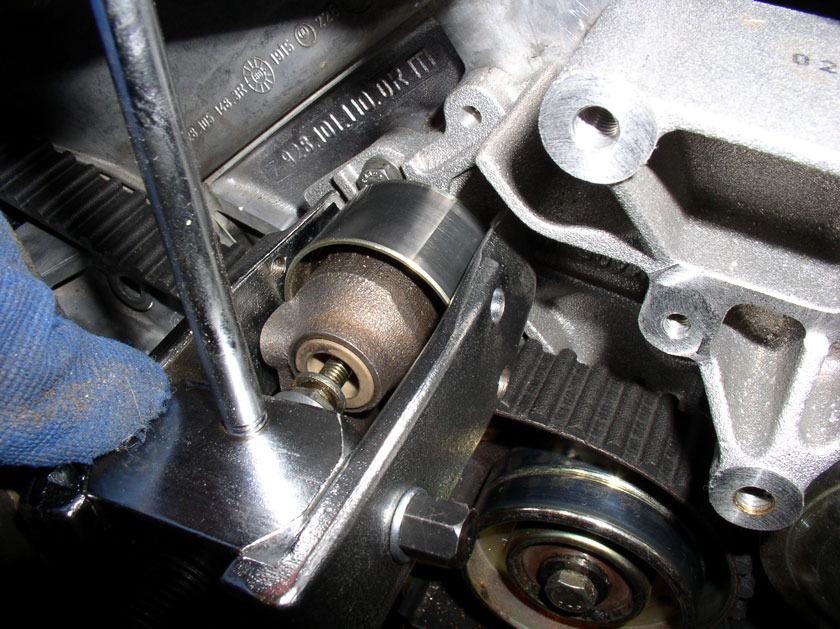
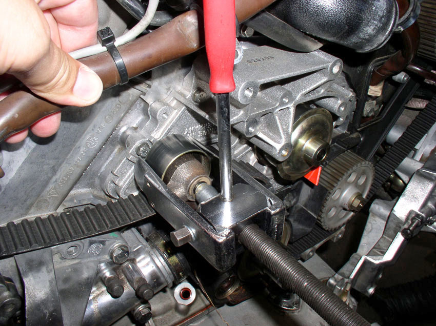
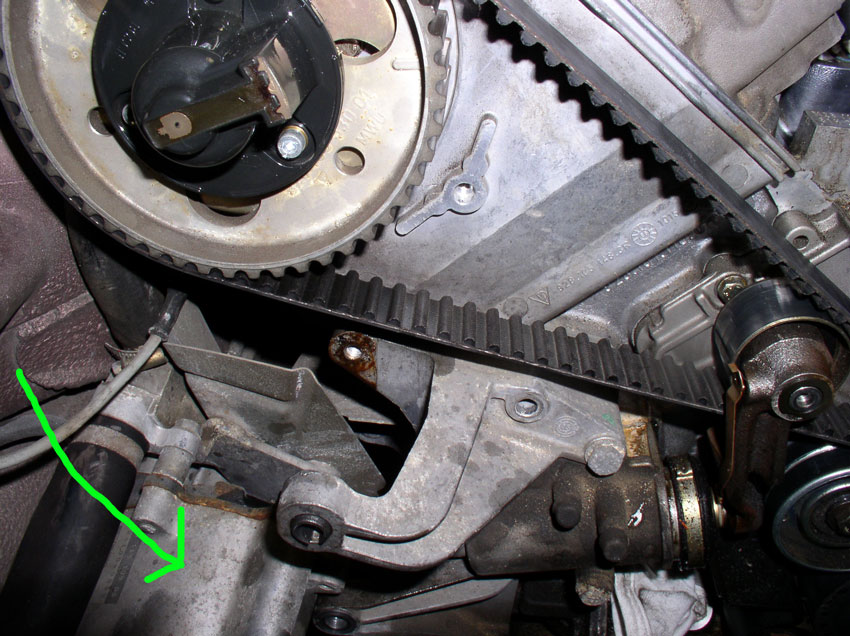
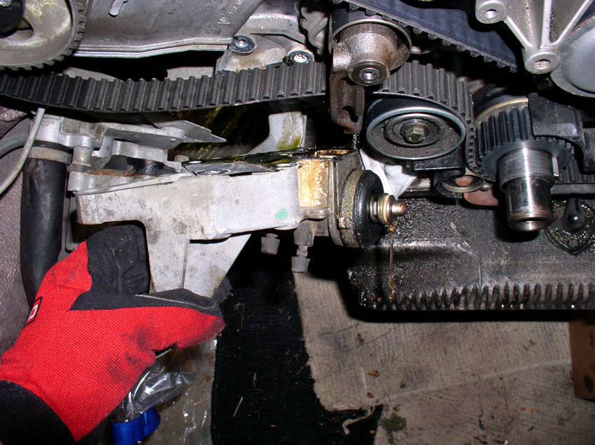
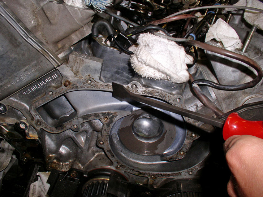
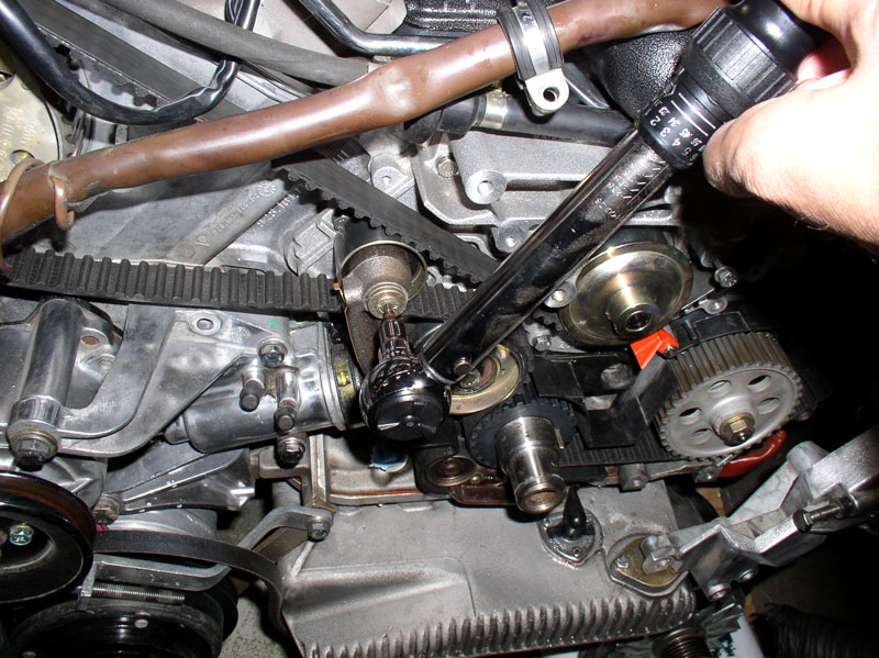
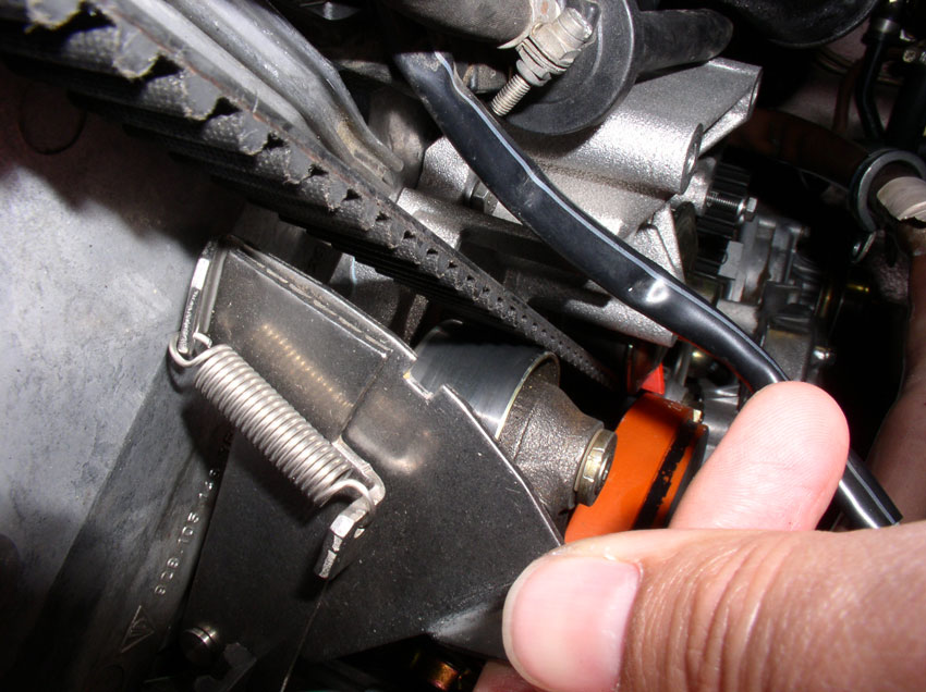
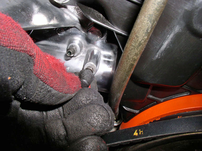
When the bolts are removed, you can use a pry bar to lever off the block and
the bracket arm as shown to break the tensioner loose. In case there is any
fluid left in the reservoir, you may want to place a rag or towel under the
tensioner before breaking it loose.
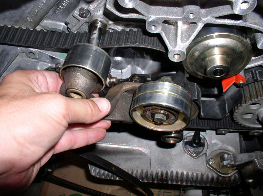
Once loose, remove the tensioner.
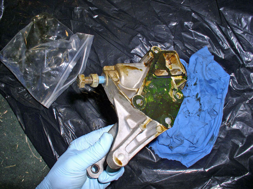
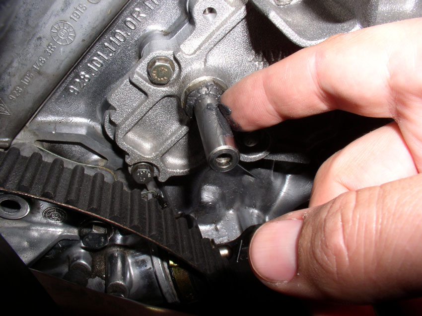
You can see the gasket was pretty much shot on this tensioner. The tensioner holds fluid (90w Gear Oil) that helps transfer engine
heat and provide lubrication to the tensioner washers inside. When the
engine warms up, it expands and causes the tension on the timing belt to
increase. The purpose of the tensioner is to provide slack in the timing belt
to compensate for the extra tension created by the expanding engine.
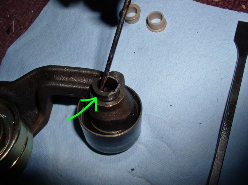
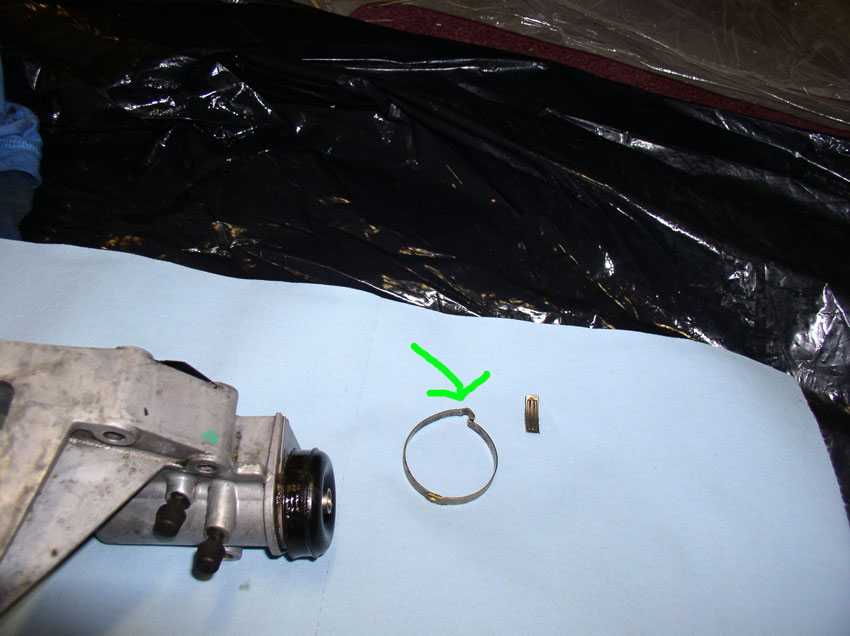
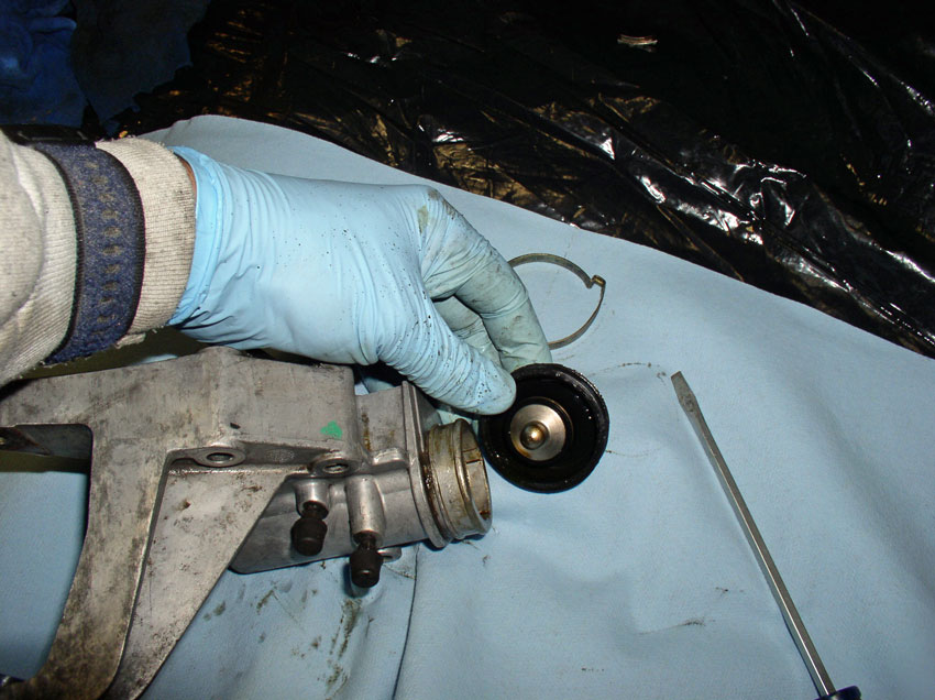
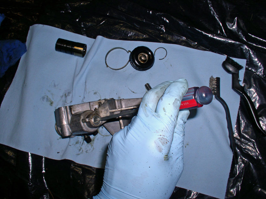
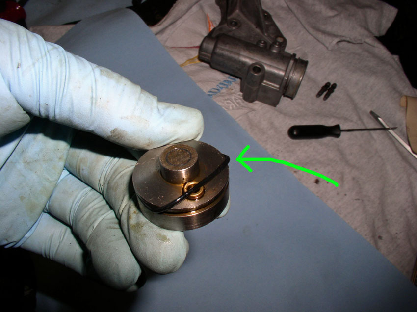
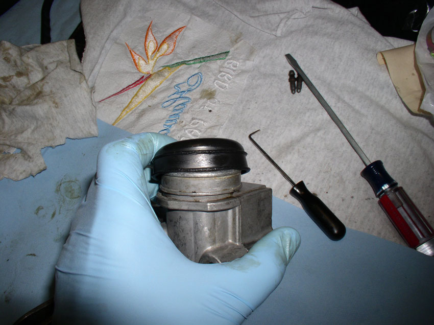
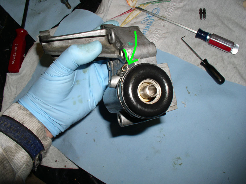
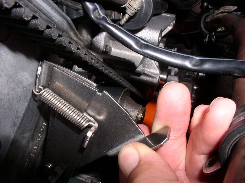
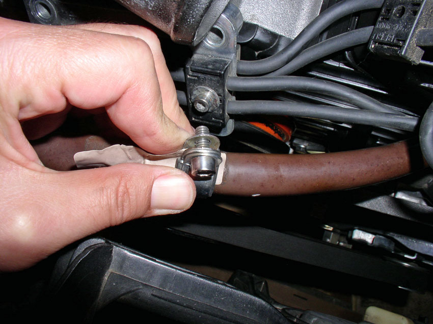
To rebuild/repair the tensioner, first remove the boot clamp. It is easily
removed by placing a screwdriver in the crimped part of the clamp and twisting
the screwdriver to open the crimp. Once the crimp is opened, the clamp can be
removed.
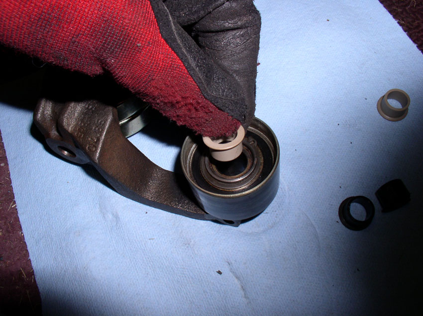
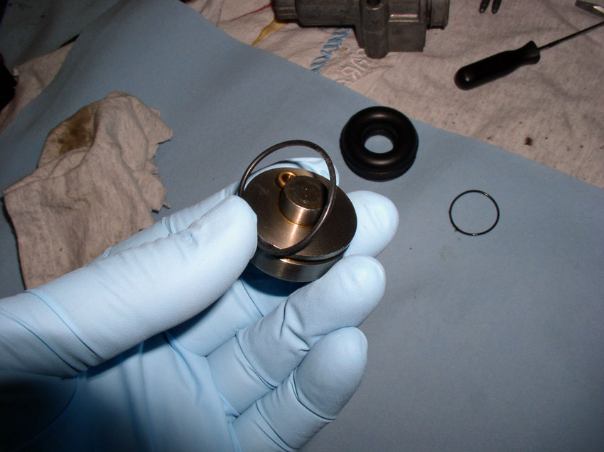
Then remove the boot as shown.
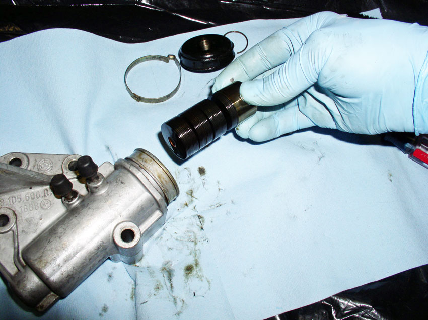
Hold the tensioner facing downward with your hand over the opening to catch the
washer assembly. Carefully remove the washer stack and leave the washer stack
in tact. There is no need to disassemble the washers unless they are caked and
stuck together. If they need to be cleaned you can remove them. There should be
a total of 35 washers. They are concave rather than flat. When they heat up,
the washers flatten out.
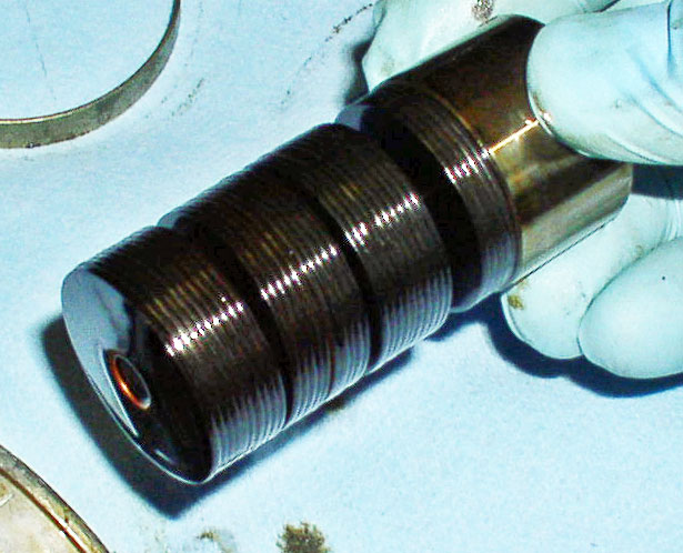
Here's a close up of the washers. They are grouped in sets of 5. If you have to
take them apart you will reassemble in the same order they were taken apart.
You will have 7 groups of 5 washers each. The 5 washers in each group will be
facing the same direction. Each group of 5 washers will be assembled on the
spindle in opposing directions and it should look like the pic
below.
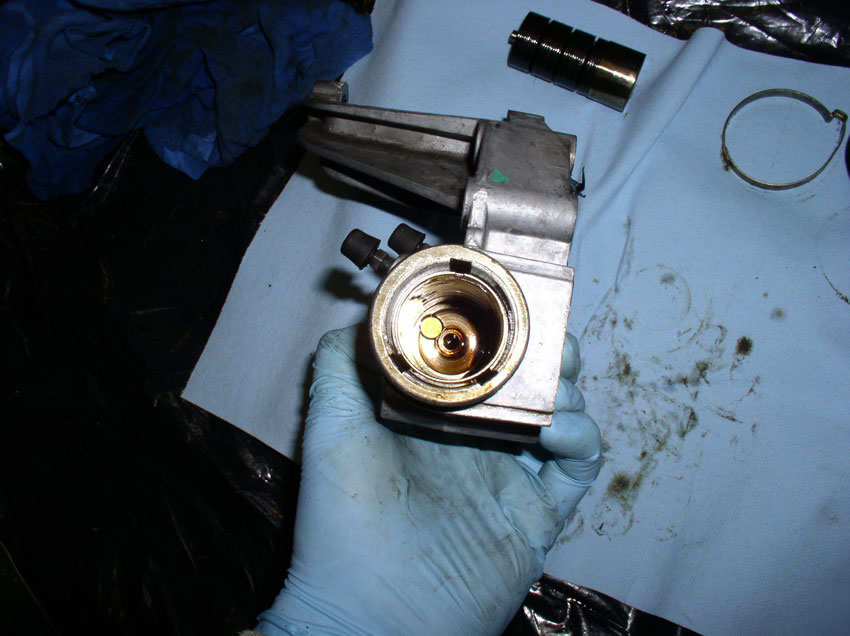
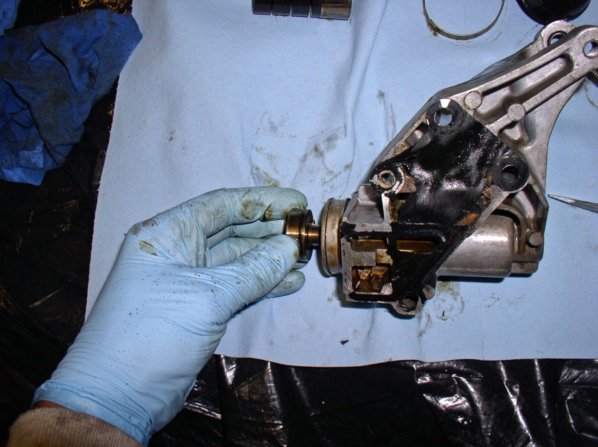
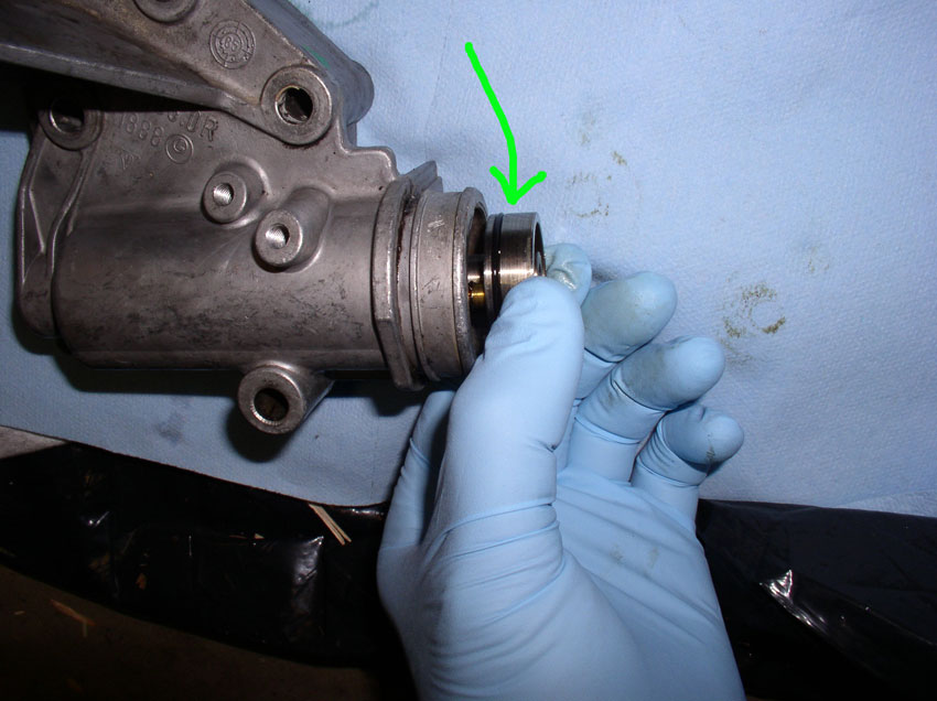
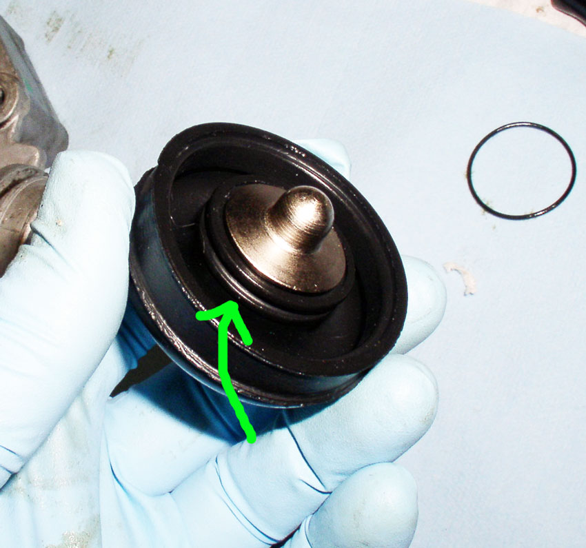
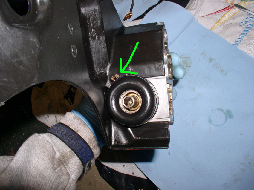
After the washer stack has been removed, you should be able to see the piston
at the bottom of the tensioner. This needs to be removed as well because it has
an O-Ring that should be replaced.
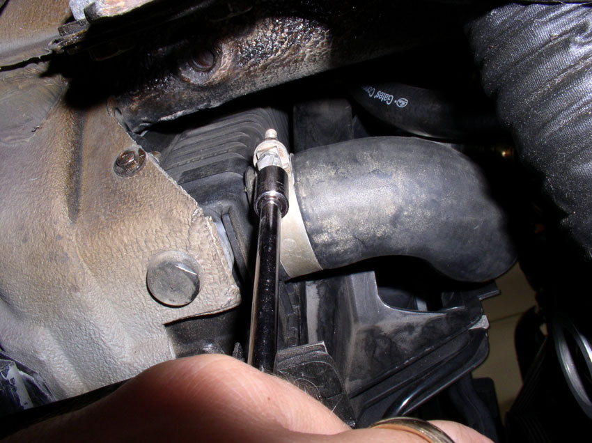
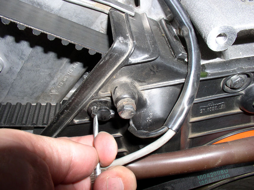
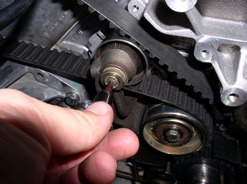
Remove the tension adjusting bolt from the rear of the tensioner housing and
insert a punch or screwdriver. You should be able to push or lightly tap the
screwdriver to push the piston forward.
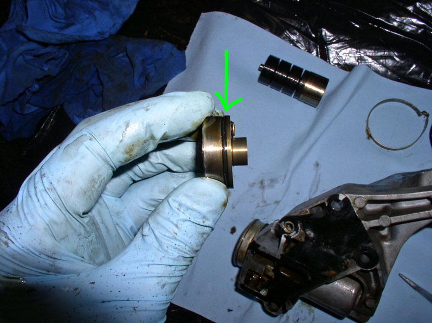
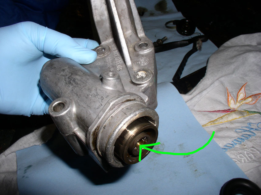
Remove the piston from the tensioner housing.
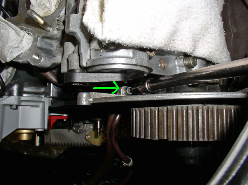
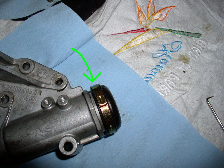
You will need to remove and replace this o-ring indicated by the green arrow in
the pic below.
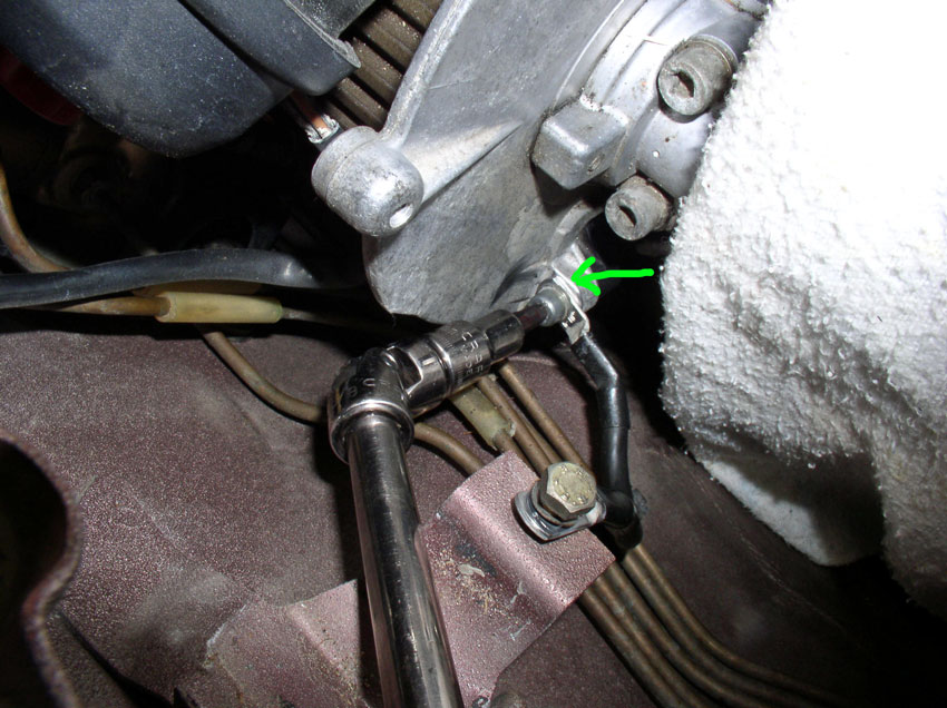
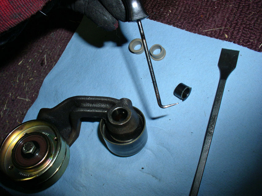
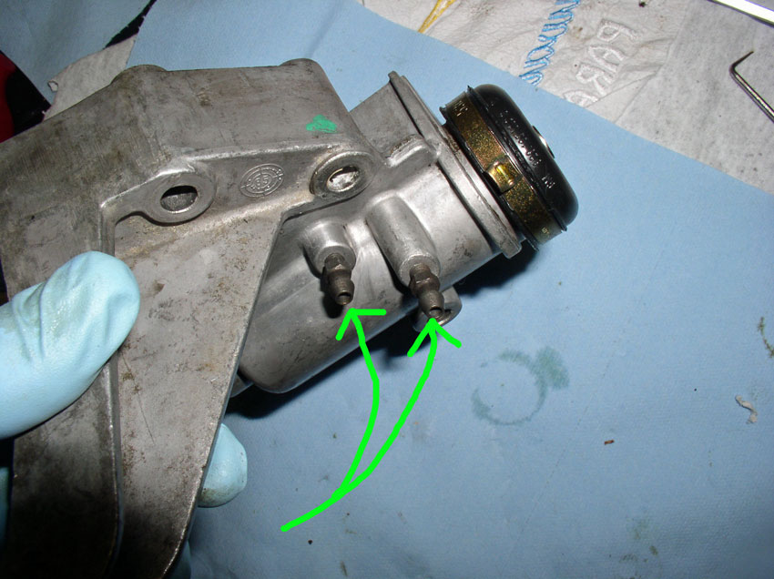
I removed and cleaned the gear oil filler and bleeder fittings next. You will
need to clean the housing including the gasket material from the housing at
this time.
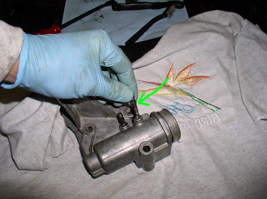
Now remove the o-ring from the piston using a pick tool
Place the new o-ring on the piston and oil the o-ring so it will install back
into the housing without deforming the o-ring.
Install the piston back into the tensioner housing and push the piston to the
bottom.
Next, install the washer stack into the tensioner housing as shown.
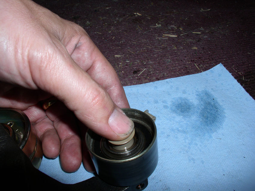
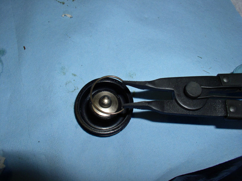
To replace the tensioner boot, you will need to remove the spring clip from the
boot.
Use a pair of circlip pliers with flat ends to remove
the spring clip.
Once the spring clip is removed. Remove the metal
center section from the old boot and transfer it to the new boot. Install the
spring on the new boot with the transferred center piece.
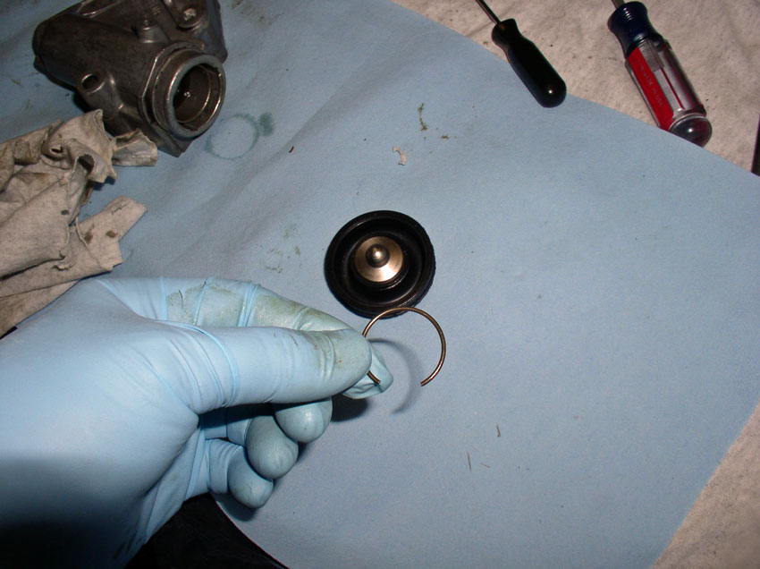
The spring clip should be fully seated in the groove in the boot as shown.
Sorry for the fuzzy picture.
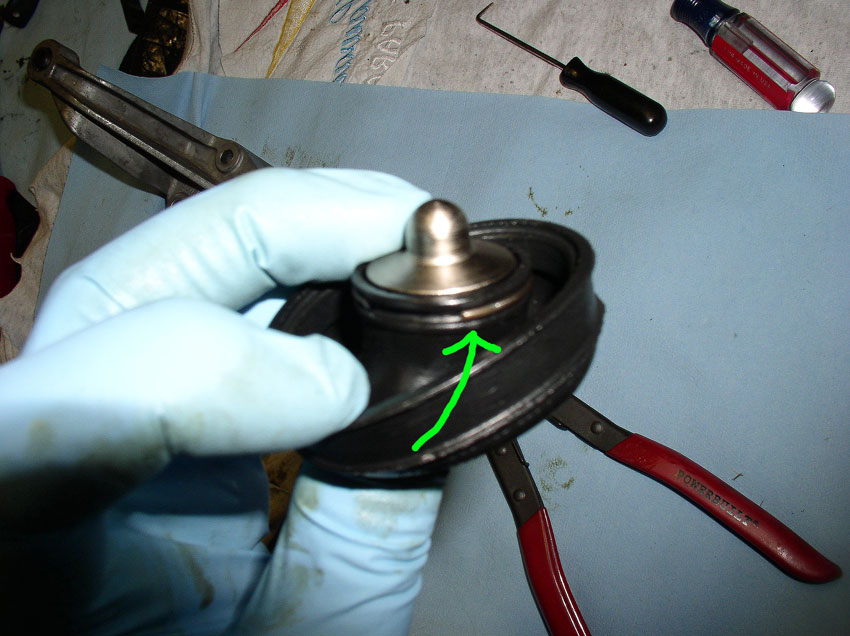
Install the boot onto the front of the tensioner housing. Ensure the boot is
fully seated over the "lip" of the tensioner housing. You can see the
lip on the housing in the picture below.
Install the new boot clamp on the boot at this time but do not crimp the clamp
yet. You will need to make sure the orientation of the crimp does not interfere
with the timing belt cover.
Fit the timing belt center cover over the tensioner as it would when installed
on the block.
Then look behind the cover to see how the crimp is oriented to the cover.
Orient the crimp so it is not touching the timing belt cover as shown below.
Now you can remove the timing belt cover and crimp the tensioner boot clamp in
place.
Lastly, re-install the gear oil filler and bleeder fittings.
Installing the water pump is next.
CH15 Installing Water Pump
If you haven't already, you will need to clean the water pump
gasket surface on the engine block. A gasket scraper works well for this.
In addition, you will need to clean the timing belt tensioner gasket off the
block as well as we will be installing the tensioner in the next section.
After the block surface has been cleaned, install the new water pump gasket. I
have installed gaskets both dry and with water pump gasket sealant. Both
methods seem to work well. I would only recommend sealant (applied to the block
surface and the water pump surface) if you have damaged surface areas that
would cause a leak. The WSM does not recommend sealant so I usually install the
gaskets dry and have had good luck.
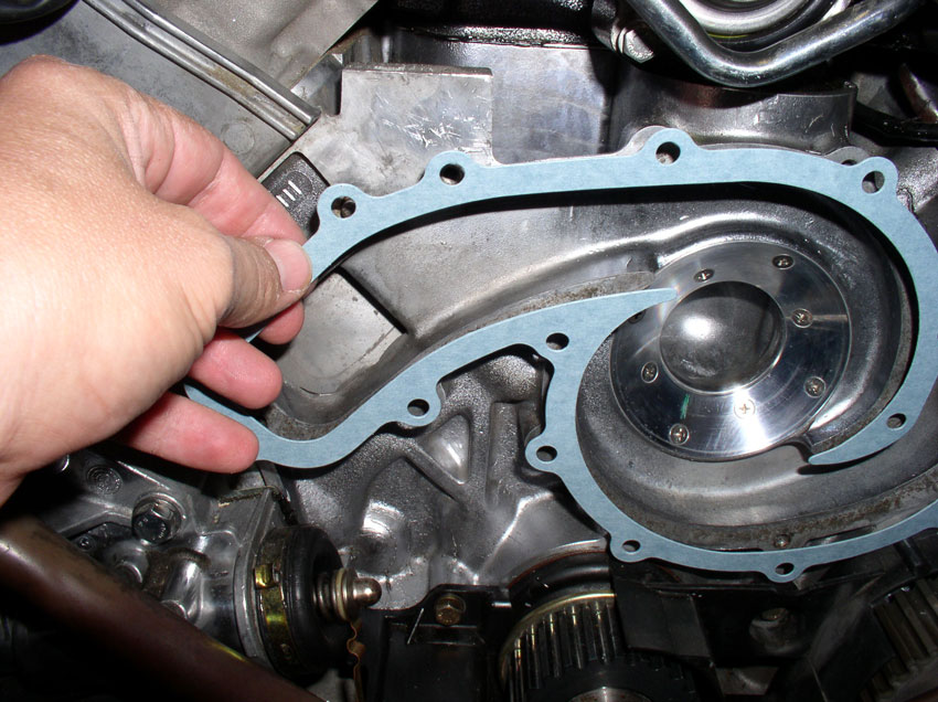
There are cutouts in the gasket that match up with the locating pins on the
block (highlighted in the pic below). This makes it
handy to hold the gasket in place while you install the pump.
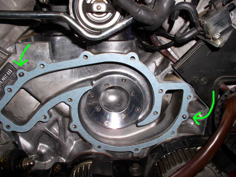
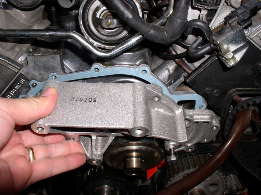
Install the pump next and press it into place over the locating pins. The pins
should hold the pump in place while you insert and hand
tighten the water pump bolts. This procedure will vary slightly
depending on whether you have a rebuilt water pump or a brand new water pump to
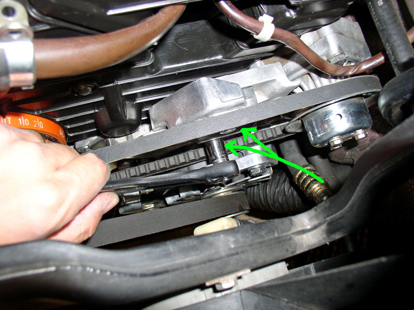
install. Pictured below is a brand new water pump.
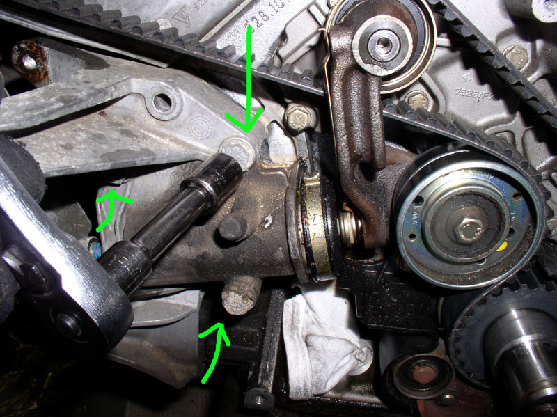
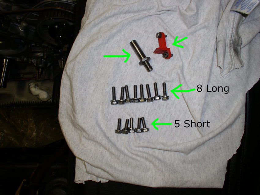
If you purchased a rebuilt water pump, you will most likely need to transfer
the red plastic timing marker and the tensioner pulley spindle (indicated by
the top two arrows in the pic below) from your old
water pump to the newly rebuilt water pump. If you purchased a new water pump,
both of these items should come already installed on the water pump. As
mentioned previously, there are 13 water pump bolts that need to be installed
at this time. Eight (8) are long and five (5) are short. The shorter bolts fit
in the recessed areas of the pump housing.
The picture below shows a rebuilt water pump being installed and you would
install the red timing marker as depicted below. Also highlighted are 2 of the
5 recessed areas for the water pump bolts. There are two of these on the right
side of the water pump pulley (as shown below) and the other 3 are on the left
side of the water pump pulley.
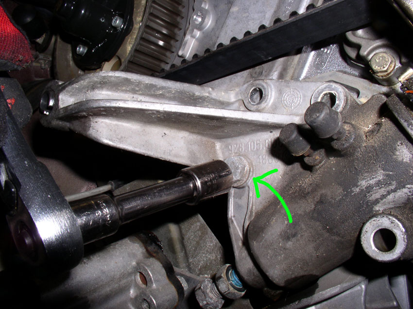
Again, with the rebuilt pump, you will need to transfer the timing belt
tensioner pulley spindle to the newly rebuilt pump. You will need to coat the
threads with water pump gasket sealant as shown below. The sealant is available
at most auto parts stores. You need to coat the threads before installing the
spindle since the spindle threads go all the way through the water pump and you
will have a coolant leak without coating these threads.
Tighten the spindle down with a 19mm wrench. If you purchased a new water pump
with the spindle already installed, this step is not necessary.
If you purchased a new water pump (as pictured below), you
will simply bolt the pump on. In either case (new or rebuilt), hand
tighten all 13 bolts. I hand tightened using the 10mm socket and extension bar
only.
There is one bolt, the 14th bolt, that needs to be
left out of the water pump casting. It is highlighted/circled
in the picture below. This bolt comes through the center timing belt cover and
through the water pump. It will be installed later when we install the cover.
After I have hand tightened all the bolts, I go back and torque all 13 bolts
down to the specified torque - 10 Nm or 7 Ftlbs (84 Inchpunds).
Next we install the timing belt tensioner.
CH16 Installing Timing Belt
Tensioner
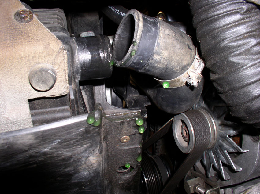
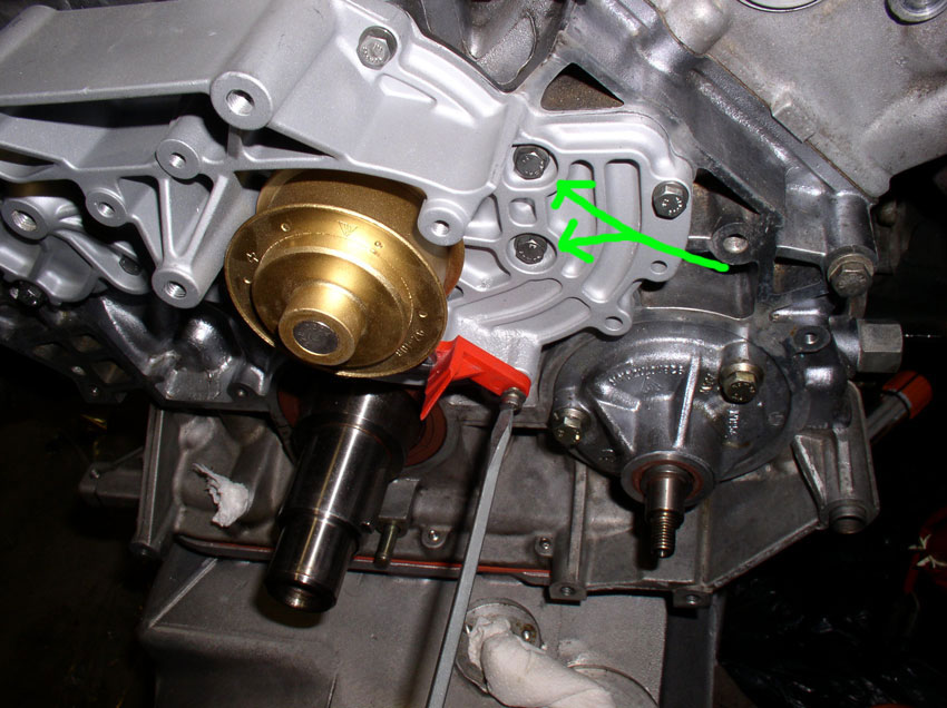
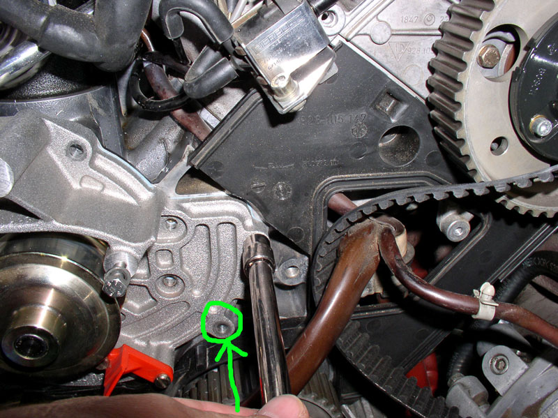
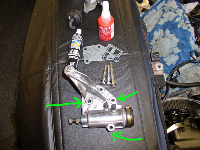
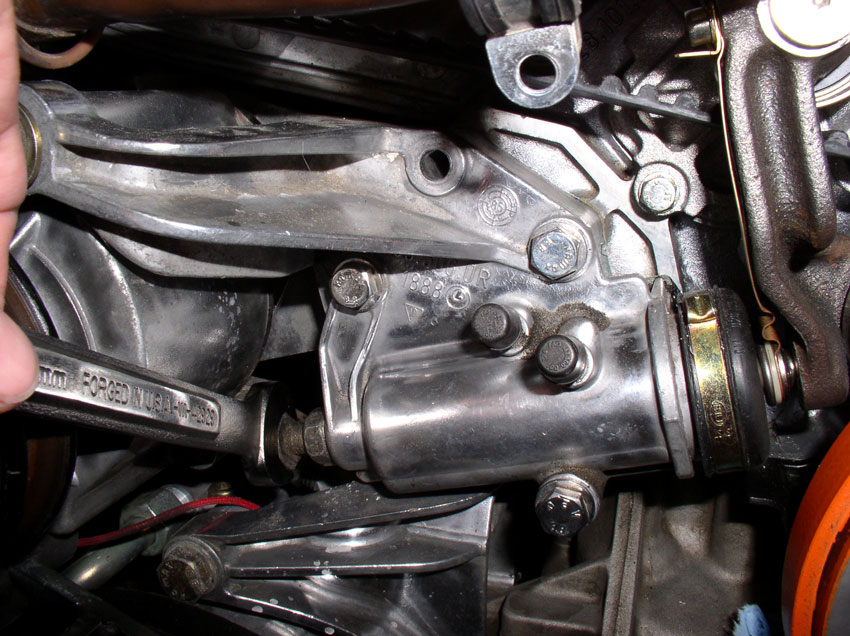
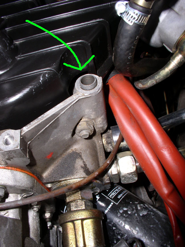
To install the timing belt tensioner, you'll need the 3 bolts that
secure the tensioner to the block. You will install the bolts in the holes
indicated by the green arrows in the pic below. The
longer bolt is used on the bottom hole as the tensioner casting is raised and
requires the longer bolt. The 4th hole in the tensioner bracket at the top is
reserved for the 13mm bolt that secures the center timing belt cover which will
be installed later.
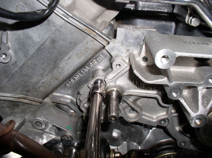
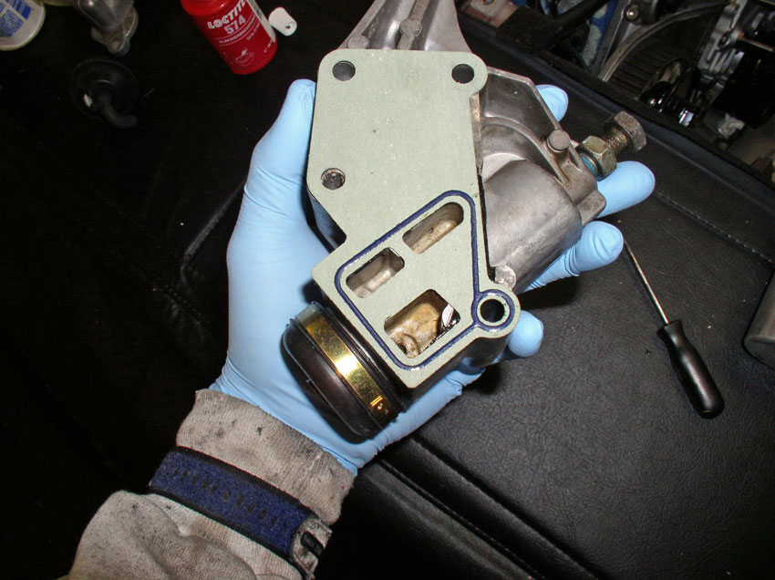
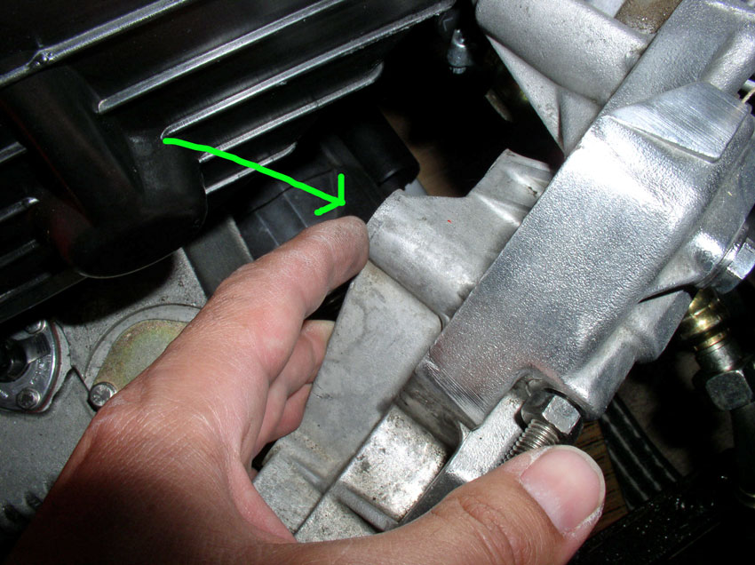
Place the gasket over the tensioner as shown in the pic
below. You can insert a couple of the bolts to hold the gasket in place while
you position the tensioner on the block. I have installed the tensioner gasket
both with sealant and dry. The WSM does not recommend sealant since the gasket
is now available (Loctite 574 was recommended by the WSM previously for metal
to metal mating of the tensioner to the block with no gasket). It's a matter of
personal preference if sealant + gasket is desired. If
you use a sealant with the gasket, ensure it is a high temperature sealant. I
prefer to install the gasket dry.
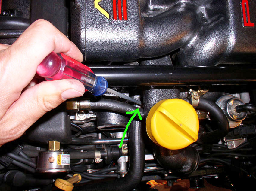
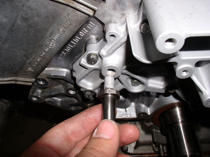
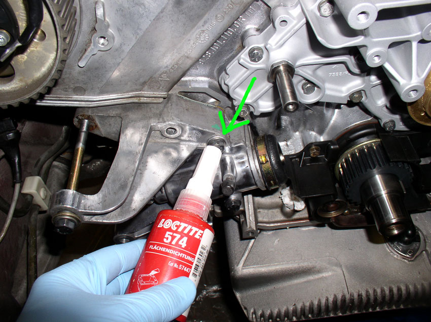
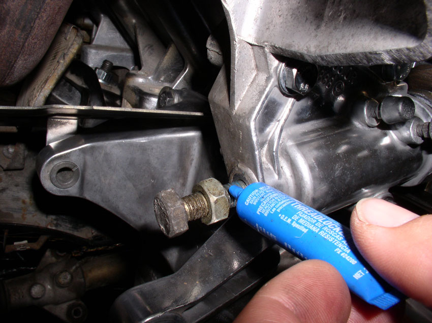
This step is optional. I seem to remember reading that a sealant such as
Loctite 574 is recommended on the threads of this bolt pointed at in the pic below. I believe it's because this particular bolt goes
through to an oil passage. Unfortunately, I can't find the reference that
states the sealant is recommended. Therefore, I would say it's optional for
now. I'll continue to look for the reference.
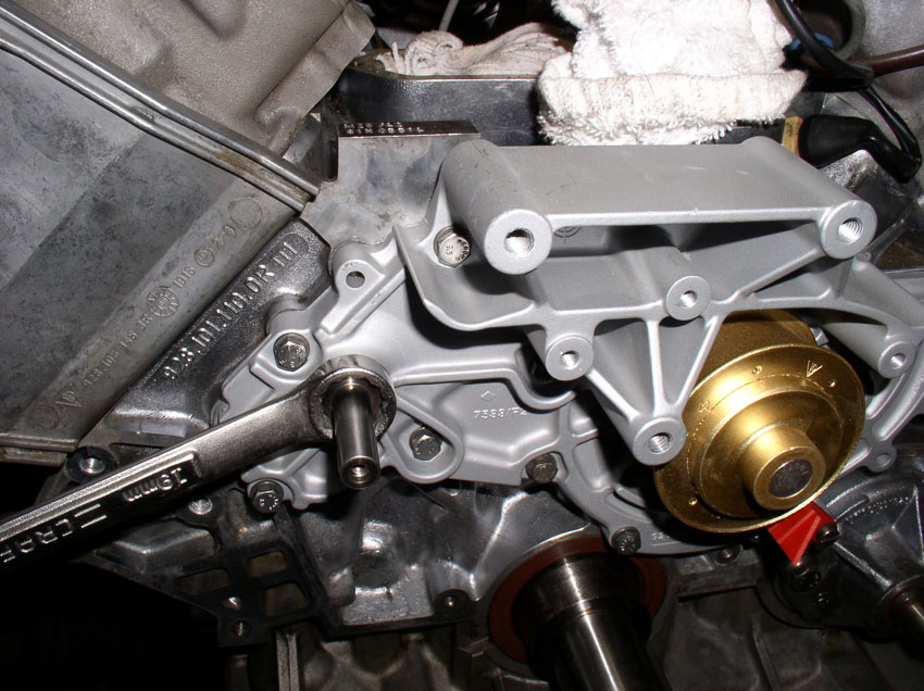
When finished installing the bolts, torque each of them down to 20 Nm or 15 Ftlbs.
Installing the timing belt tensioner pulley is next...
CH17 Installing Timing Belt
Tensioner Pulley
In order to install the Timing Belt Tensioner Pulley, you will
need to partially install the new timing belt. First, feed the two loose ends
of the two engine wiring harnesses through the timing belt. Then route the
timing belt around the timing belt gear on the crankshaft, around the oil pump
gear and up and over the driver's side cam gear and under the water pump
pulley. Do not pull it tight - we'll do that in the next Chapter. Also, do not
wrap timing belt around the passenger side cam gear - you will need the extra
slack. This is mainly to keep the timing belt out of the way yet somewhat in
place and slack in order to install the tensioner pulley. Before installing the
tensioner pulley on the spindle located on the water pump, I applied some
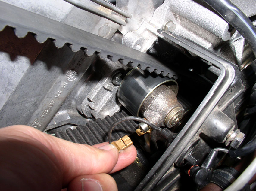
synthetic grease to the spindle to ease installation and future removal - see pic below.
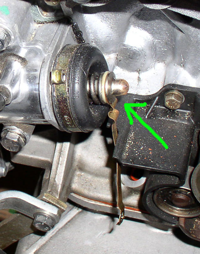
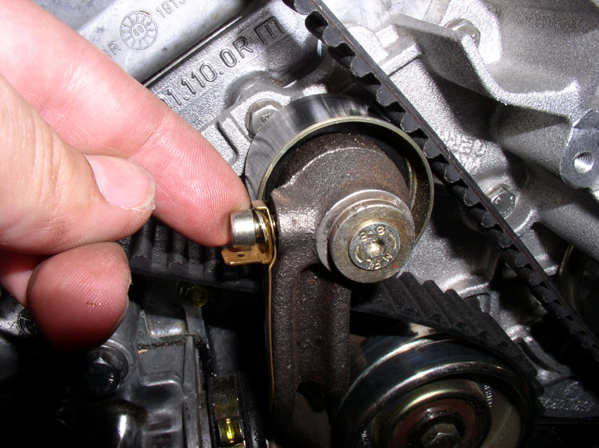
Install the Timing Belt Tension Warning Contact on the end of the tensioner
boot fitting as shown below.
Next, position the tensioner pulley assembly as pictured below. Begin to slide
the idler pulley (top pulley) over the freshly greased spindle.
Press the idler pulley on to the spindle until it is fully seated as shown
below. Also note how the timing belt is routed in the pic.
We'll install the allen head
bolt later after we've installed and tightened the belt and we're sure we don't
need to take the belt off again.
Finally, ensure the Belt Tension Warning Contact fits into the Tensioner Pulley
arm as shown below.
Now we'll route the timing belt and set the initial tension....
CH18 Installing Timing Belt and
Setting Tension
Before routing the timing belt, ensure the tension adjustment bolt
at the back of the timing belt tensioner is out as far as possible to allow
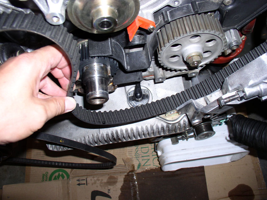
maximum slack in the belt while installing. Start the installation by routing
the timing belt around the crankshaft gear as shown.
Pull the timing belt tight as you route the belt around the oil pump gear next
as shown.
Continue pulling the timing belt tight as you route the timing belt over the
driver's side cam gear. Ensure the white mark on the cam gear lines up with the
"V" notch in the cam gear backplate as
shown. If they are not liined up, you will need to
move the cam gear so the paint mark lines up with the notch. This is depicted
after the next couple of steps on the passenger side cam gear.
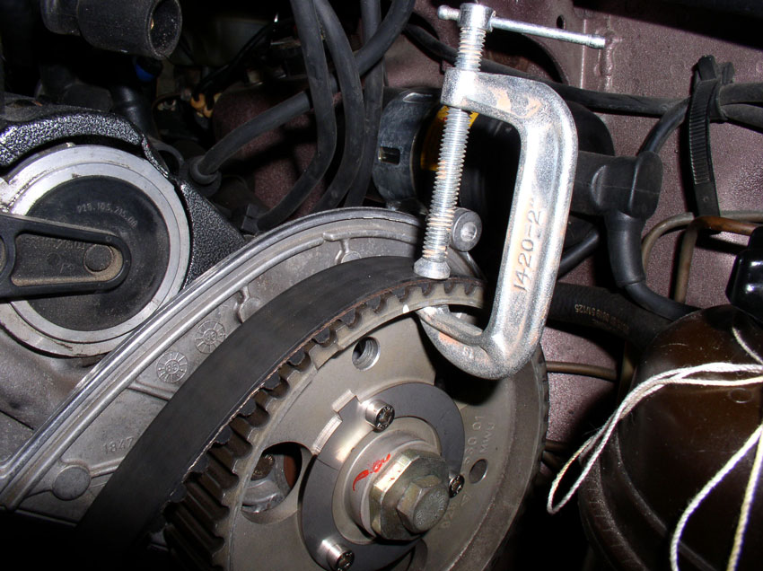
Once the belt is installed on the driver's side cam gear, you can (optionally)
hold the belt in place using a small "C" clamp.
Route the timing belt under the water pump pulley, keeping the belt tight.
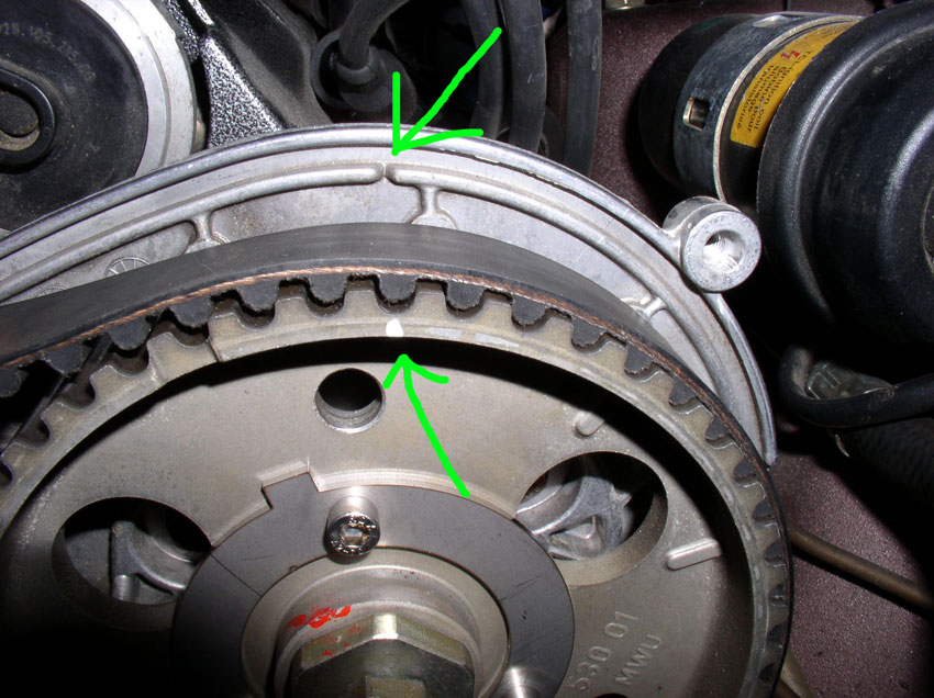
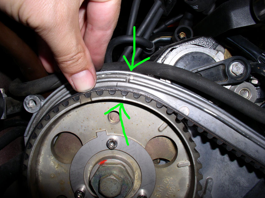
Route the timing belt over the passenger side cam gear next. However, my cam
gear was not lined up with the "V" notch as you can see in the pic below. It had "backslid" about one cam gear
tooth width.
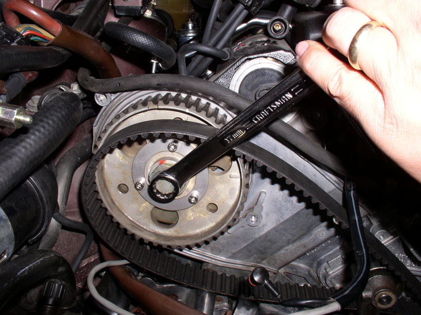
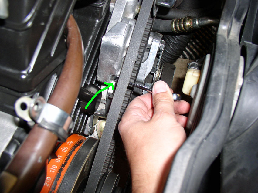
To line up the cam gear, use a 17mm long handled wrench to turn the cam gear as
shown in the picture below. Only turn the cam gear in the clockwise direction.
If the white mark is past the "V" notch in the backplate,
you will need to rotate the cam gear all the way around clockwise again to line
up the paint mark with the "V" notch.
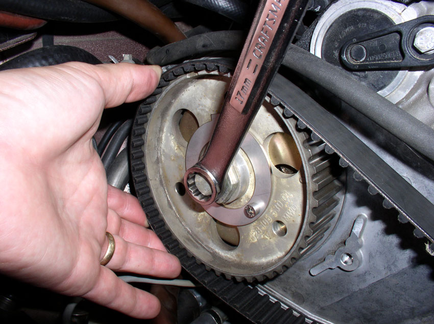
Once the paint mark is lined up with the "V" notch, hold the cam gear
in place with the wrench while you pull the timing belt tight and slide it onto
the gear with the other hand as shown.
When the belt is correctly positioned on the cam gear, the paint mark should
line up with the "V" notch as shown below.
If everything looks "normal" at this point, we need to tighten the
tensioner pulley bolt. Install the 4mm allen
head bolt and washer into the pulley spindle as shown.
Then torque to no more than 10 Nm or 7 Ftlbs making
sure the allen socket is
fully seated in the bolt head to minimize chances of striping the bolt.
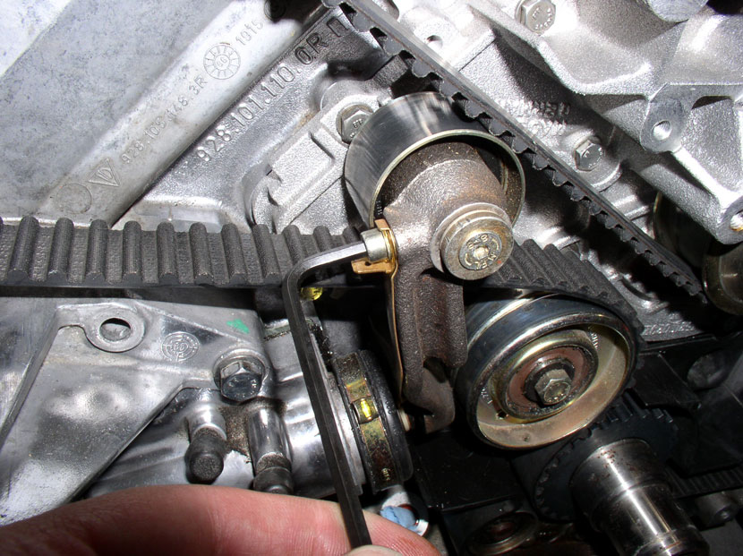
Next, attach the tension warning contact strip to the tensioner knuckle using
the 4mm allen head bolt as
shown. Note how the electrical connector blade is oriented. Make sure it is not
oriented facing the front of the car as it may interfere with the timing belt
cover when the electrical lead is connected to it.
Then snug down the allen
head bolt with a wrench or socket. I did not feel the need to torque this bolt
down as it seems smaller than an M6.
Now tighten the timing belt tensioner adjustment bolt using a 17mm wrench. Turn
the bolt in a clockwise direction until all the slack is taken out of the
timing belt and the timing belt is snug around the tensioner pulley.
Next, we'll check the initial tension but we have to rotate the engine to the
TDC position in order to get an accurate tension reading. To prepare for
rotating the engine, we'll install the vibration dampener on the crankshaft.
First, I applied a thin layer of synthetic grease to the end of the crankshaft
to ease the installation and future removal of the vibration dampener.
Next, install the timing belt guide onto the crankshaft as shown.
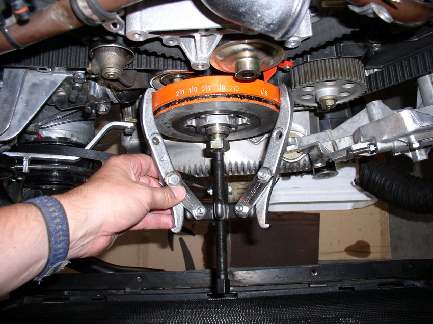
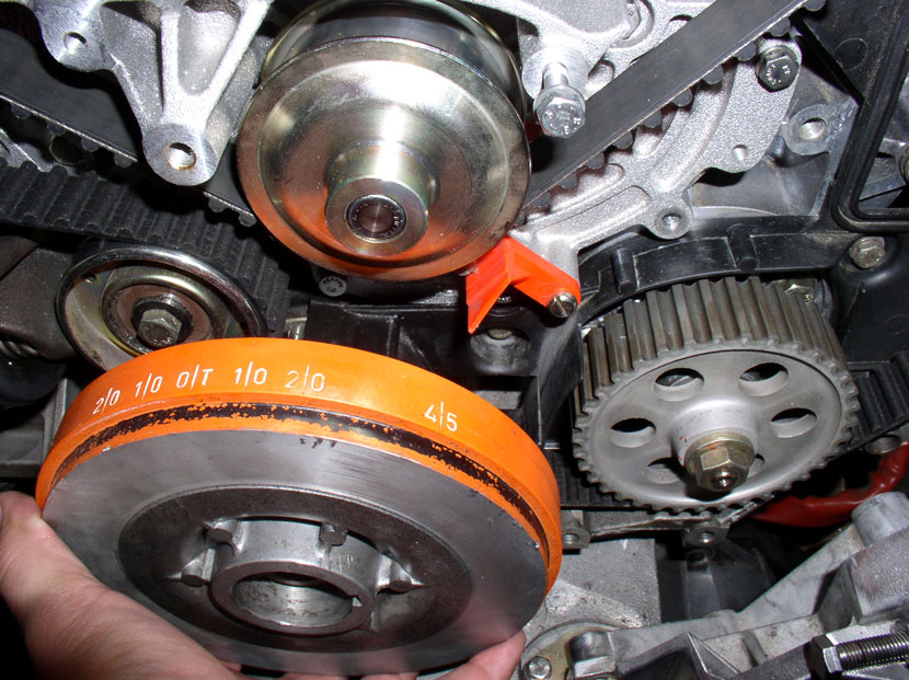
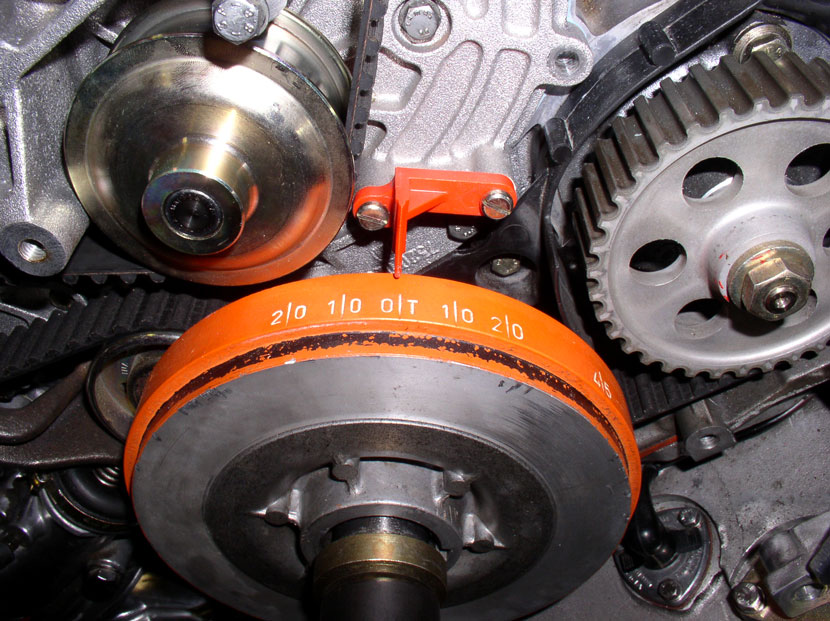
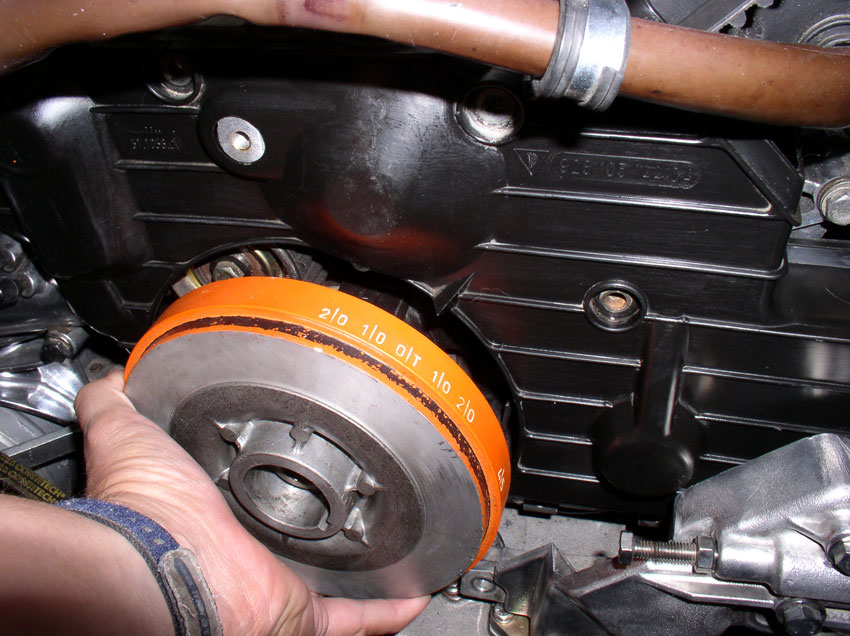
Install the vibration dampener onto the crankshaft as shown. The "45"
mark should line up with the red timing indicator as shown below.
Install the 27mm crankshaft bolt and washer.
From underneath the car, remove the flywheel lock tool.
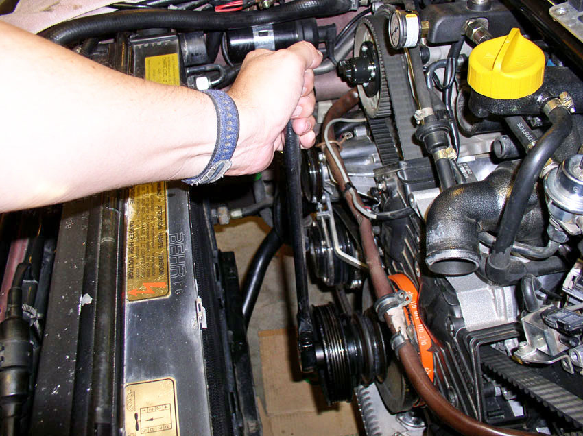
Using a 27mm socket and long handle socket wrench, turn the crankshaft
clockwise at least two revolutions....
...until you come to the "OT" mark on the dampener indicating Top
Dead Center (TDC). Verify you are at TDC by inspecting the cut "V"
notches in the cam gears line up with the cut "V" notches in the cam
gear backplates for both cam gears.
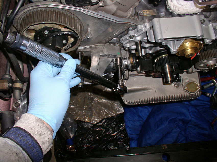
Once at TDC, I checked the belt tension with the Kempf tool. As you can see, it
was too loose.
Before the final tightening, you can (optionally) apply some thread locker Blue
to the threads of the tension adjustment bolt.
Then tighten the adjustment bolt again clockwise (I tightened it about 2
revolutions) and repeat the process of rotating the crank two revolutions to
TDC again and check the tension. Repeat this process until.....
The tension is properly set according to the tool as seen below (i.e., the
indicator is in the middle of the notch on the tool). When the tension is
correct, tighten the locking nut (17mm) on the tensioner adjusting bolt (back
of the tensioner).
CH19 Installing Center Timing
Belt Cover and Routing Engine Harness
Next, route the engine harnesses that were detached previously
back to their respective locations. Starting with the larger
harness first, push the end of the 14-pin plug underneath the passenger side
cam gear as shown.
Continue pushing the harness up behind the passenger cam gear until you can
grasp it from behind the gear near the engine lift hook.
Pull the harness through enough to connect the 14-pin plug to its receptacle
next to the battery charging post as pictured.
Connect the red power cable to the battery charging post and tighten down the
11mm charging post bolt as shown.
Place the harness in the harness clamp next to the engine lift hook and tighten
down the 10mm clamp nut as shown.
Re-connect the A/C compressor power lead to the harness. The power lead
connects to a blade terminal located inside the square plastic connector as
shown below.
Next, route the smaller engine harness in behind the power steering fluid hoses
and behind the power steering fluid reservoir bracket as shown.
Connect the end to the terminal box as shown and secure the lead by tightening
down the phillips screw.
Close the protective cover lid over the connection box.
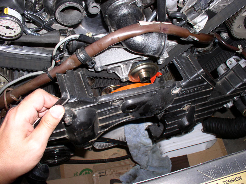
To prepare for installing the center timing belt cover, I removed the vibration
dampener for ease of installation. You can actually install the cover with the
dampener in place as well. Do not secure the cover yet.
With the cover pulled out a couple of inches, attach the belt tension warning
wire to the blade connector attached to the tensioner pulley knuckle as shown
below. The blade connector on the pulley knuckle can be oriented down or toward
the back as shown in the pic.
Ensure the wire is free from contact with the timing belt or idler pulley as
shown.
Since I removed the vibration dampener for the cover install, I needed to
re-install the timing belt guide on the crankshaft....
....followed by installing the vibration dampener on the end of the crankshaft
next.
Install the 13mm bolt on the left side of the cover next.
Install and hand-tighten the long 10mm bolt near the center of the cover as
shown below. This is the bolt that goes through the water pump casing.
Install and hand-tighten the two 10mm bolts at the top of the cover as
indicated by the green arrows below.
Torque the three 10mm bolts to 10 Nm or 7 Ftlbs.
Torque the 13mm bolt on the left side of the cover to 20 Nm or 15 Ftlbs. The center cover is now installed. Next, install the
air pump onto the tensioner bracket and insert and hand-tighten the long 13mm
pivot bolt as shown in the pic below.
Next, we'll fill the tensioner with oil....
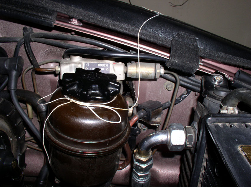
CH20 Filling Tensioner with
Gear Oil
To fill the tensioner, I used 90w gear oil. You can also use motor
oil according to the
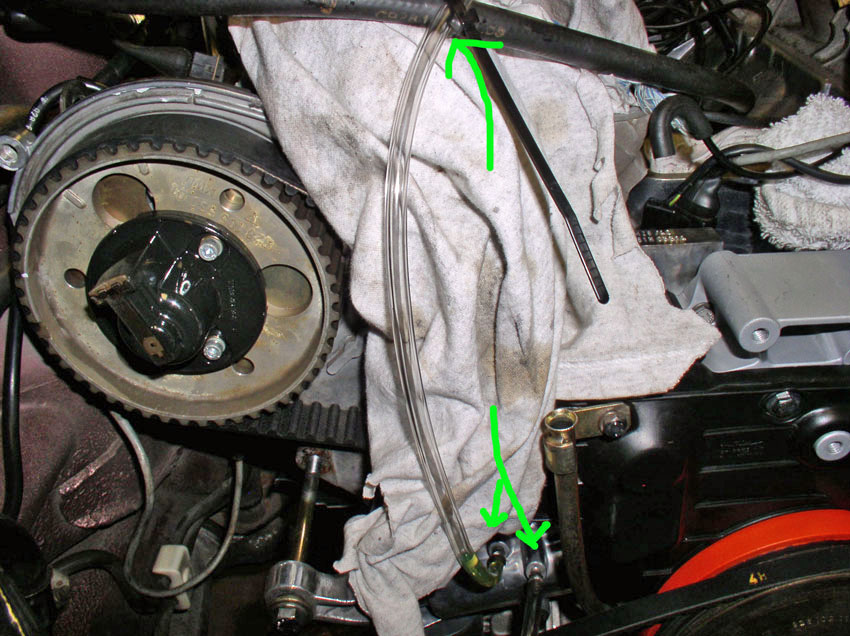
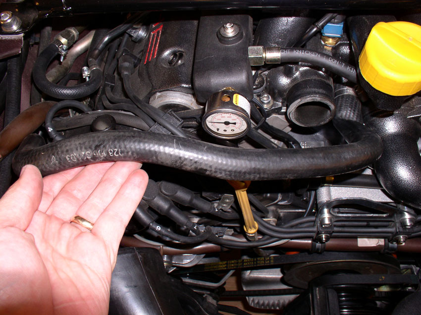
Next, fill the tube on the left that's connected to the fill port with 90w gear
oil or clean motor oil. Fill the tube to the top as shown in the picture below.
It will take a while for the tensioner to fill with this method so you may
leave it unattended and work elsewhere on the car while it is filling. You will
be watching to see if any oil comes out the bleeder port as seen through the
plastic tube.
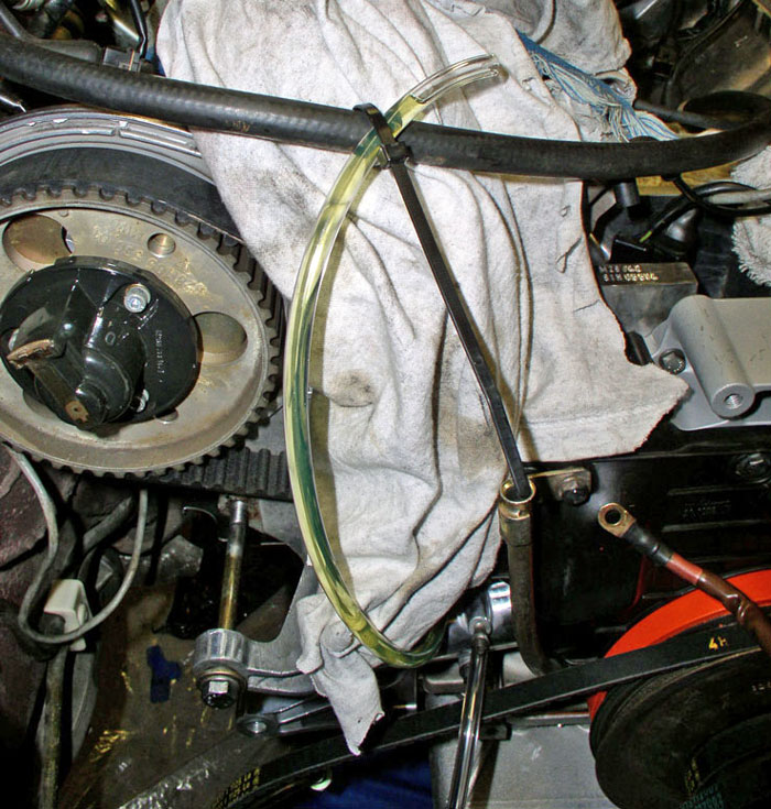
You may need to fill the hose 2 or 3 times before you finally see oil coming
out the bleeder port as shown in the pic below. The
tensioner is full.
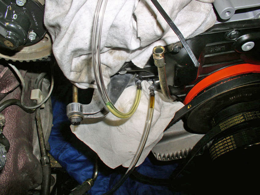
At this point, remove the plastic tubes and tighten down both of the fittings.
Only about 3 Ftlbs should do it.
Attach the protective covers next and you're done.
CH21 Installing Power Steering
Pump and Alternator
Install the Power Steering pump and bracket next. You will notice
there is a locating pin on the engine block shown in the pic
below.
The locating pin is mated to this locating hole in the PS bracket. Place the PS
bracket on the locating pin and press into place.
Next, install the 17mm bolt as shown below and hand tighten.
Install the two 13mm bolts and hand tighten as shown.
The bracket can now be torqued down. You will torque
the 3 bolts just installed and indicated by the green arrows below. The two
13mm bolts to the left are torqued to 20 Nm or 15 Ftlbs. The 17mm bolt is torqued
to 40 Nm or 30 Ftlbs.
Next, bring up the alternator and insert it onto the bracket....
...and use the long 17mm pivot bolt to help locate the alternator on the
bracket. Hand tighten the pivot bolt.
Bring the tension adjusting bracket up and install it with the 17mm bolt as
shown below. Hand-tighten the bolt at this point. This
bolt will be torqued down after the belt is installed
and tensioned.

Next, we will install the upper cam covers....
CH22 Installing
I started with install the passenger side upper cam cover. Place
it into position.
You will notice a locating pin on the upper bolt. The cam cover also has a lip
that fits over the cam gear back plate. Make sure the lip is over the back
plate and the locating pin should slide into place.
There are 2 bolts that secure the cover in place. Install the long 10mm bolt as
shown and hand tighten.
Install the shorter 10mm bolt in the upper part of the cover as shown.
Torque both bolts down to 10 Nm or 7 Ftlbs.
The driver's side cam cover also has a locating pin as shown below and a lip
that fits over the cam back plate.
Install the cover ensuring the lip is over the back plate.
This cover has three 10mm bolts that secure the cover. Install the 10mm bolt
that also secures the flappy vacuum solenoid bracket as shown below.
Install the 10mm bolt at the top of the cover as shown.

Finally, install the "hidden" 10mm bolt at the cam cover opening as
shown.
Torque all three 10mm bolts to 10 Nm or 7 Ftlbs.
Next, we install the fan shroud....
CH23 Installing Fan Shroud
First lay the fan shroud fans facing down over the top of the
radiator as shown in the picture. We'll be installing the wiring harness first.
Connect the fan plugs first. The nearest plug on the harness goes to the left
fan as shown in the pic while the plug at the end of
the harness goes to the right fan.
Next, lay the harness into the spring clips attached to the fan shroud backing
as shown below. Leave the harness out of the 2 top most clips because you will
need the slack in the harness to maneuver the shroud into place.

Tilt the shroud up and begin sliding it down the backside of the radiator.
Grab the air pump hose and pull upward as shown and leave in place.
Tilt the shroud downward on the left side and position into place as shown in
the pic below.
Position the left side of the shroud into place where the locking lip engages
the radiator tank as shown in the pic.
Maneuver the right side of the shroud down and into place. The tight spot will
be with the upper oil cooler hose fitting. With some maneuvering, it will slide
into place.
Make sure the locking lip on both sides of the shroud engage the radiator as
shown in the pic and ensure the shroud is in front of
the aluminum radiator tabs at the top of the radiator as shown below.
From underneath, ensure all the locking tabs are fully inserted into their
respective slots at the bottom of the shroud as shown below.
Lastly, secure the shroud to the radiator using the two 10mm screws as shown.
Then insert the wiring harness into the 2 top most clips in the fan shroud from
a few step back.
Next, we'll install accessory belts and pulleys.....
CH24 Installing Accessory Belts
and Pulleys
Start installing the accessory belts from the inside out (A/C
compressor first and Alternator last). Position the A/C belt pulley into place.
Place the belt on the pulley as shown.
Place the pulley on the crankshaft as shown below. Also ensure the air pump
belt adjusting bracket is positioned between the A/C belt
as shown by the arrow in the pic below. Install the
13mm bolt that secures both support brackets to the engine block and hand
tighten.
Install the PS and air pump belts on their respective accessory pulleys and lay
the belts at rest as shown below.
Position the accessory pulley into position as shown.
Attach the PS and Air pump belts to the pulley as shown below. The opposing
forces of the belts will keep the pulley suspended.
Install the alternator belt on the alternator and attach it to the pulley as
shown below. Then place the pulley onto the end of the crankshaft.
Install the 27mm crankshaft bolt and washer next.
It was easier to start threading the bolt into the crankshaft from underneath
the car.

Re-install the flywheel locking tool in the flywheel inspection opening and
secure with bolts.
Using a 27mm deep 6-point socket and long handle torque wrench, torque the
crankshaft bolt to 295 Nm or 217 Ftlbs.
Remove the flywheel locking tool.
Re-install the flywheel inspection cover plate and 13mm bolts.
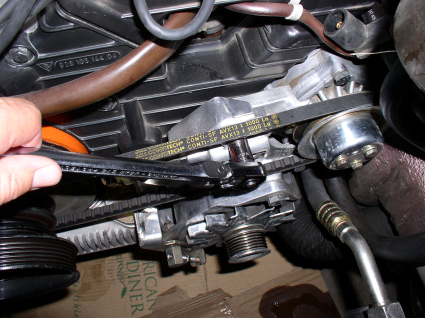
Now you can start tensioning the belts. I started with the A/C compressor belt.
Use a 13mm gear wrench to turn the adjusting nut until the tension is correct.
Then tighten the 17mm locking bolt a shown.
Tighten the rear A/C compressor pivot bolt - 17mm.
Followed by tightening the front A/C compressor pivot bolt -
17mm. The front is a little tight to get to with the wrench.
Tighten the PS pump belt next. Use a 13mm gear wrench to tighten the tension
adjustment bolt until the belt tension is correct.
Then tighten the 13mm lock nut on the adjustment bolt as shown.
Lastly, tighten the two 13mm locking bolts on the front of the PS bracket as
shown. You can torque to 20 Nm or 15 Ftlbs.
Air pump belt is next. Using a stubby 13mm wrench, tighten the tension
adjustment nut as shown in the pic below until the
tension is correct.
Then tighten the 13mm locking bolt as shown.
Tighten the 13mm bolt that secures the air pump and A/C pump belt tension adjustment
support brackets. You can torque to 20 Nm or 15 Ftlbs.
Lastly, tighten the 13mm air pump pivot bolt as shown. You can torque to 20 Nm
or 15 Ftlbs.
Alternator belt is next. Using a 13mm gear wrench, tighten the tension
adjustment bolt until the belt tension is correct.
Then tighten the 13mm adjustment bolt lock nut.
On the backside of the lower tab, tighten the 17mm lock nut as shown.
Tighten the 17mm alternator pivot bolt as shown.
The last bolt to tighten on the alternator is the adjustment bracket to engine
block bolt - 17mm. I do not have a clear picture of the bolt but here is a
picture for reference.
Tighen
down this bolt as shown.
Connect the alternator cooling hose to the air guide as shown.
Next we'll install distributor caps, dipstick and spark plug wires....
CH25 Installing Distributor
Caps, Dipstick, Spark Plug Wires
Position the center engine lift hook and spark plug wire bracket
toward the front of the engine.
Install the small 5mm allen
head bolts into the engine harness clamps - there are two of them.
Install the bolts/clamps onto the engine lift hook and hand
tighten as shown.
Next, attach the engine lift hook to the water pump casing with the two 6mm allen head bolts as shown. Tighten
down the two bolts.
Then tighten down the two 5mm allen
head bolts for the engine harness clamps.
Secure the small front engine harness to the driver's side cam cover with the
plastic clip as shown.
Starting with the passenger side distributor cap, attach the coil wire to the
bottom of the distributor as shown.
Secure the distributor cap to the cam cover using an 8mm socket or flat blade
screwdriver. Tighten all three screws. Install the driver's side distributor
cap in the same manner next.
Connect all the spark plug wires to their respective distributor in their
respective order. If you still have the sticker on top of the radiator, it will
show you which order the spark plug wires should be connected to the
distributor. If not, for the passenger side distributor (standing in front of
the car), the plug order on the distributor from left to right should be 4, 6,
7, and 1. For the driver's side distributor (standing in front of the car), the
plug order on the distributor from left to right should be 5, 2, 3, and 8.
Connect the belt tension warning harness lead to the connector on the cam cover
as shown. Push the plug in until the locking tab clicks.
Ensure the dipstick tube o-ring is seated on the bottom of the tube as shown.
Maneuver the tube down the front of the cam covers and insert the end into the
oil pan.
Ensure the tube is fully seated in the oil pan as shown.
Install the 10mm bolt that secures the dipstick tube to the cam cover as shown.
Install the dipstick into the tube.
Next, we'll install the coolant hoses....
CH26 Installing Coolant Hoses
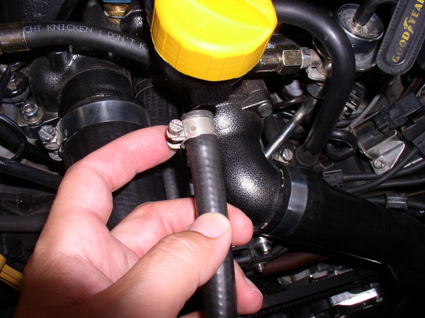
I started by installing the heater return hose. Install the hose
onto it's fitting on the thermostat housing as shown. Ensure the clamp is
oriented so you can access it with a screwdriver from above.
Tighten the hose clamp with a flat blade screwdriver as shown.
Install the upper radiator hose next.
Install the hose on the radiator and ensure the clamp can be accessed from
above and to the left of the hose. Then tighten the clamp with a 10mm socket or
flat blade screwdriver.
Attach the other end to the thermostat housing as shown. Ensure the clamp can
be accessed from above. Tighten the clamp with a 10mm socket or flat blade
screwdriver as shown.
Install the bleeder hose next. Ensure the clamp can be accessed from above with
a screwdriver. Also ensure the hose lays on top of the
upper radiator hose.
Tighten the bleeder hose clamp with a flat blade screwdriver as shown.
Attach the fan shroud harness to the fan shroud using the plastic harness clip
as shown.
Install the charging post plastic cover and secure it with the plastic cover
nut as shown.
Attach the air pump filter elbow pipe to the air pump hose as shown.
Install the elbow into the bottom of the filter housing as shown. Tighten the
clamp with a flat blade screwdriver.
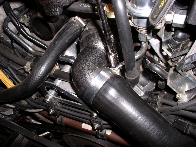
Maneuver the lower radiator hose down between the engine and fan shroud as
shown.
Connect the upper end to the elbow at the thermostat housing. Ensure the clamp
can be accessed from above.
Tighten the clamp with a 10mm socket or flat blade screwdriver.
From underneath, orient the clamp so it can be accessed from underneath the car
and install the hose onto the radiator. Tighten the clamp with a 10mm socket or
flat blade screwdriver.
Next, we'll wrap up....
CH27 Wrap Up
Install the PS fluid reservoir clamp next.
The clamp should still be apart from the removal process. Insert the end of the
clamp behind the bracket and under the lip of the reservoir as shown.
Tighten the clamp with a long flat blade screwdriver.
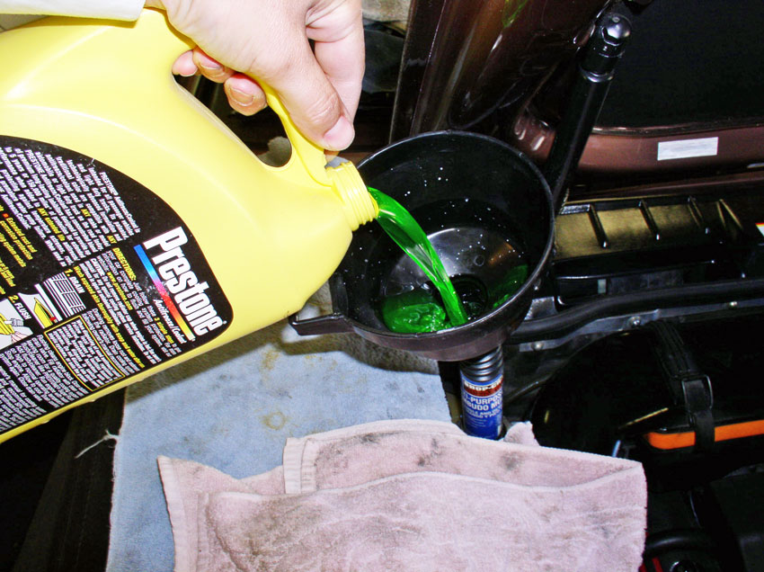
Fill engine block, radiator and coolant reservoir with coolant. I use a 50/50
mixture of coolant and distilled water but coolant strength is a personal
preference.
Reconnect the negative battery terminal to the body chassis as shown (or
reconnect the negative cable to the battery if you went that route).
Re-install the intake air tubes.
While the car is still on the jack stands, it's a good time to check for
coolant leaks or timing belt tensioner oil leaks. You can start the car while
it's on the stands and let it run for a few minutes while checking for leaks.
If no leaks, turn off the car and re-install the belly pans. Install the front
belly pan first, followed by the rear pan.
Take the car carefully down from the jack stands and take it for a test drive.
Run/drive the car until the operating temperature is reached,
turn on the heater to max heat and run for a few minutes. After the car cools
down, recheck the coolant level and top off, if necessary. That's about it!
Hopefully, this has been a helpful guide for this common maintenance procedure.
Please feel free to comment or add advice as I'm always looking to improve the
quality of a post like this. I'm particularly interested in whether or not
breaking up the procedure into chapters than can be "searched" with
the search function in order to quickly locate a section of the procedure that
is of particular interest. THANKS for reading!!
Version: