1987 Water
Pump Failure Block Repair Procedure (w/pics)
A couple of weeks ago, I completed this repair using Greg (Brown)
and Steve's newly developed block repair tool. I picked up the tool from Greg
at Sharktoberfest and started the repair the
following weekend. It took me approx. 2 weekends to disassemble, effect the
repair, and reassemble. Someone more experienced than I could certainly do it
in a long weekend, I believe. Here's the link to the thread I started when the
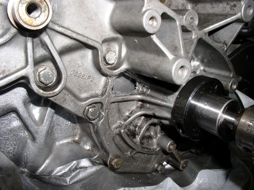
failure was first noticed - it includes pictures of the damaged block and the
defective rebuilt water pump: http://forums.rennlist.com/rennforum...ater-pump.html
I found the instructions that Greg provided to be EXCELLENT! Since I'm not a
pro wrench, I read through the instructions 2-3 times completely before
starting while comparing the descriptions and pictures to the parts/tools
supplied in the kit. Then, while making the repair, I double checked everything
before cutting/drilling to minimize mistakes. Although the repair seemed
tedious, it is definitely doable WITH patience.
The quality of the kit was GREAT. Everything was clean and extra bits are
supplied in case they are dulled during use. All in all, it was a great
experience and I'm happy to report the temperatures are lower than before the
repair (although I have to qualify that statement since I no longer have 100
degree ambient temps to compare to the baseline reading I had previously -
guess I'll have to wait until spring/summer for the true check).
I thought I'd share the process I used for those interested in this repair. It
should be very close to the instructions supplied with the kit. Greg's
instructions were excellent and I really can't add anything to his instructions
(except a few pics, of course!). This sequence of pics assumes you already have the front of the engine
disassembled with the water pump removed.
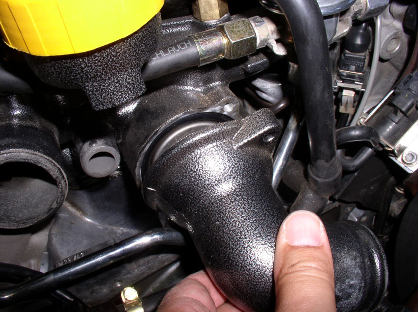
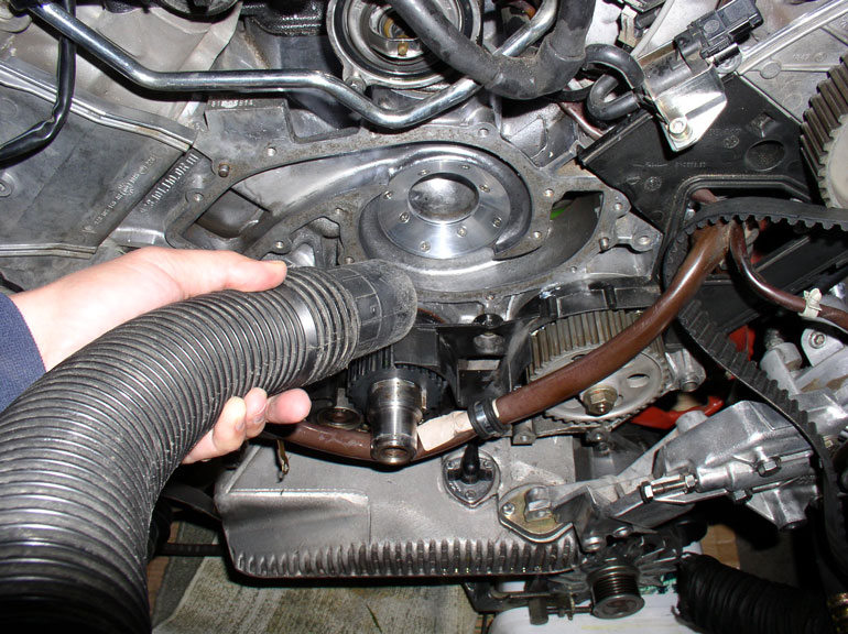
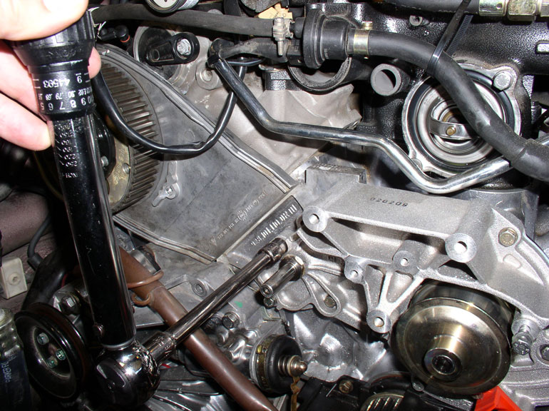
Normally, you would not remove the upper radiator hose elbow pipe for a TB/WP
removal but I found it easier to have it out of the way for this repair.
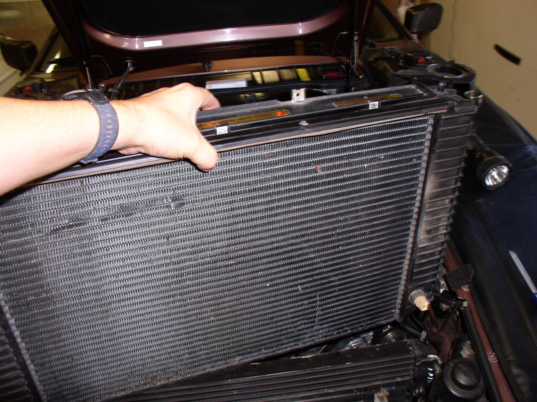
You will also need to remove the radiator if you use the supplied drill (which
I did).
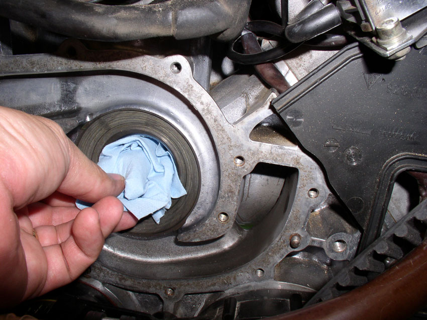
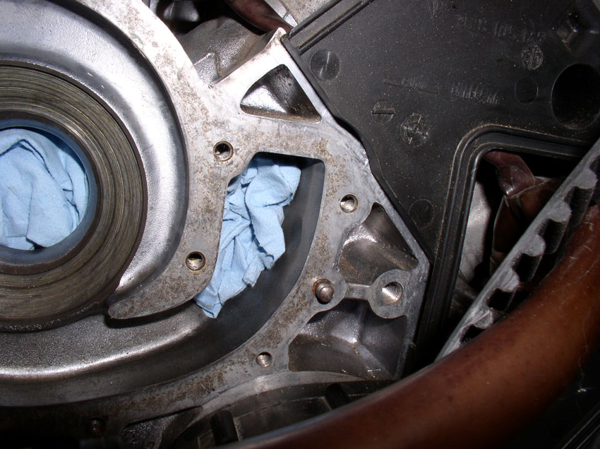
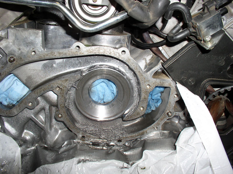
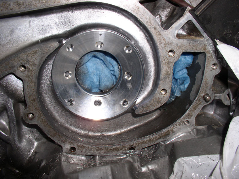
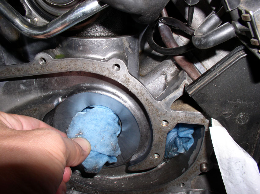
Next, I stuffed the main coolant opening with shop towels in an attempt to keep
the filings and oil out of areas I didn't want.
Also stuffed the coolant ports on the left...
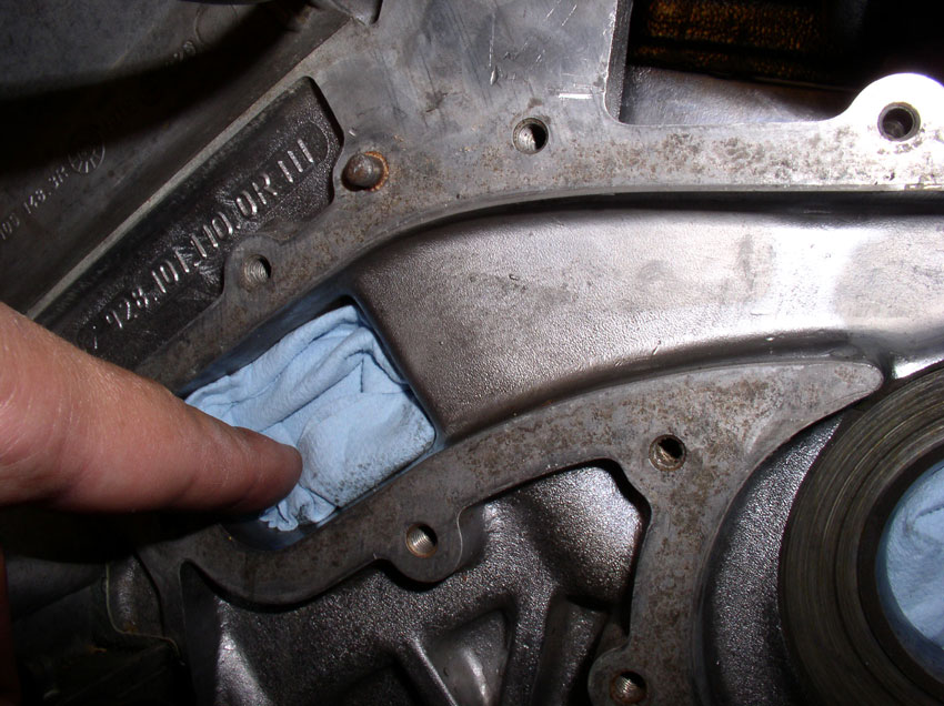
...and right.
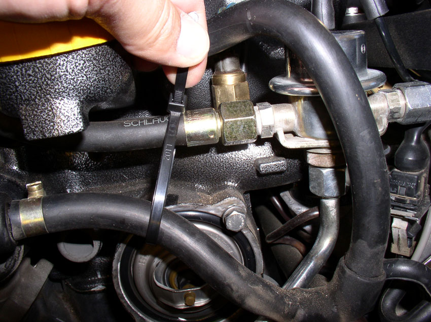
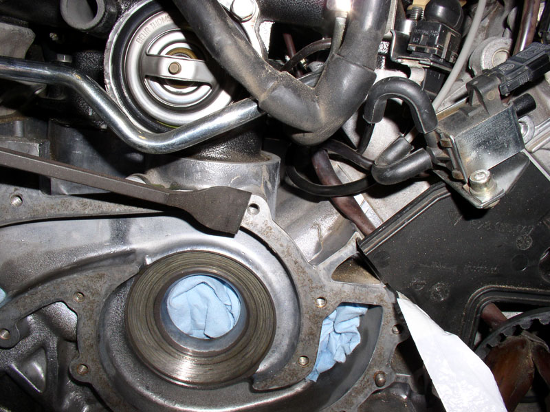
Next, I zip-tied the fuel vapor inlet hose up out of the way.
...and routed the engine harness under the crank shaft to keep it out of the
way.
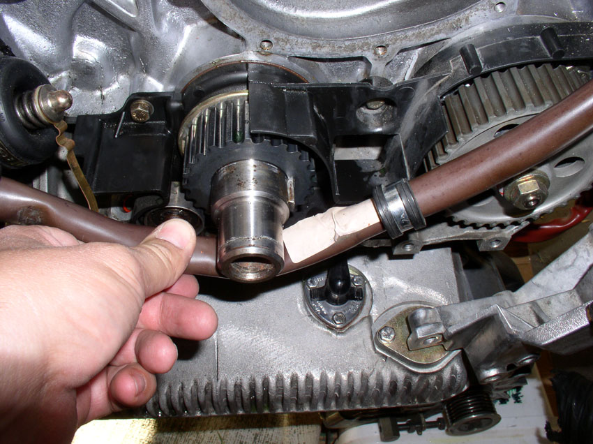
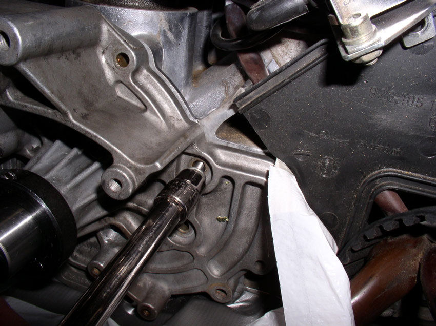
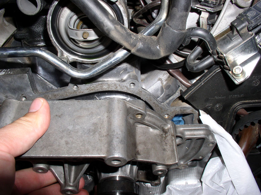
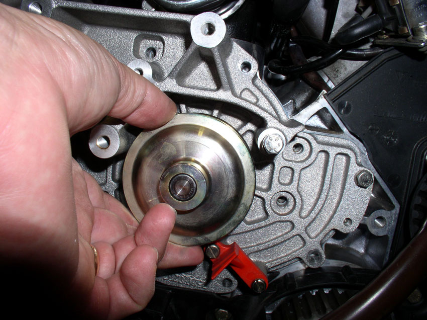
With these out of the way, you should have clear unobstructed access to the
water pump and block.
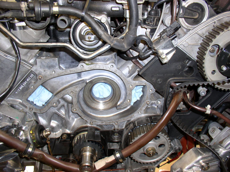
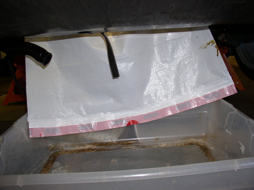
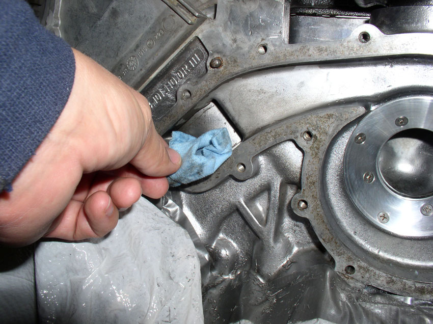
Next, I attached some duct tape to a plastic bag (garbage bag) and secured the
tape under the water pump mating surface on the block in order to catch and
deflect as much of the cutting oil as possible and keep it from getting on the
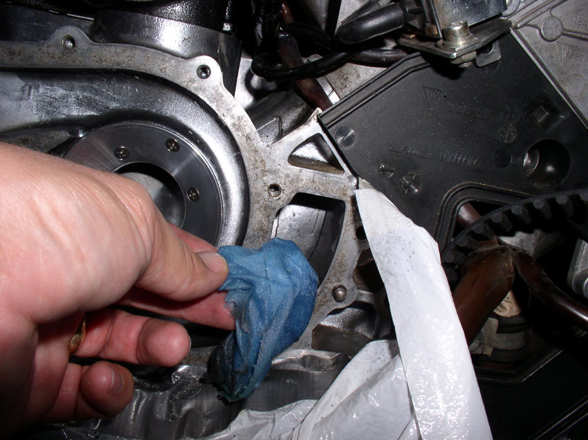
lower section of the block. I also stuffed a small rag in the opening directly
under the water pump mating surface and above the crank shaft since there was
no surface to attach the tape to.
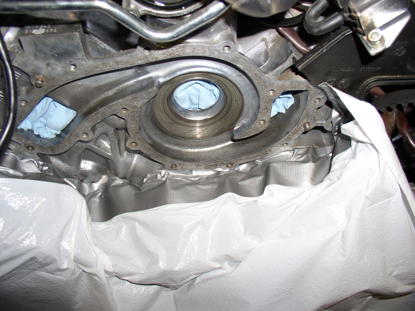
Let the plastic drape down into a sweater type plastic storage container -
remember to buy your wife a replacement container! This arrangement actually
worked out well and made clean up very easy.
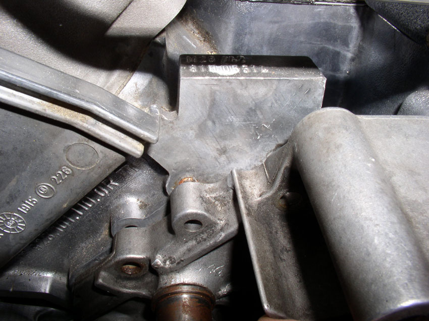
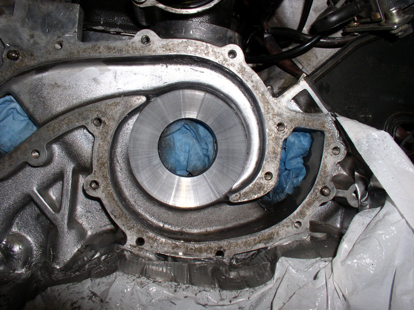
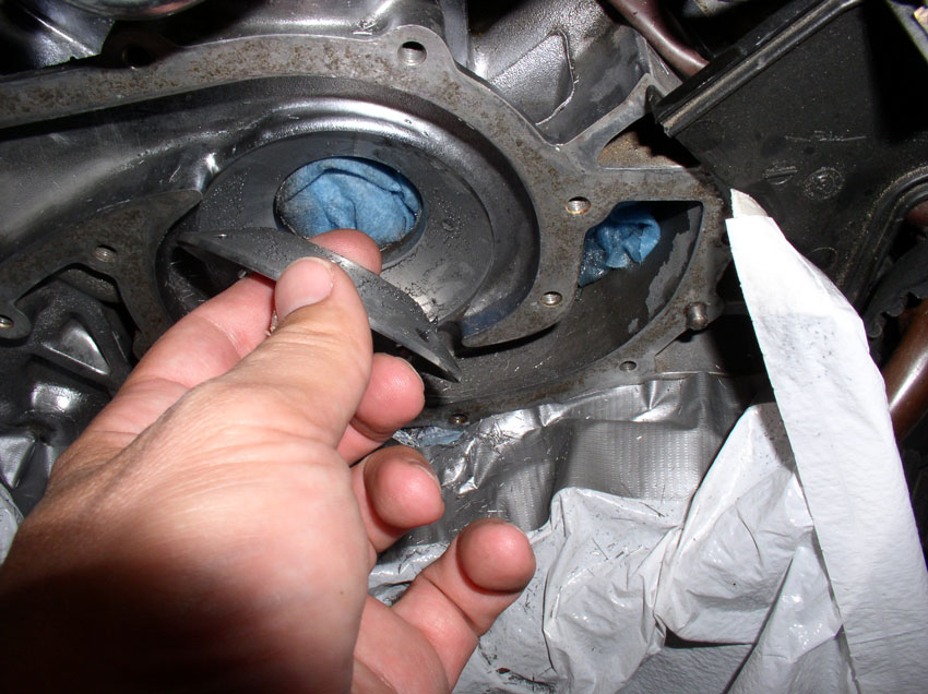
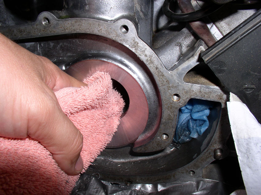
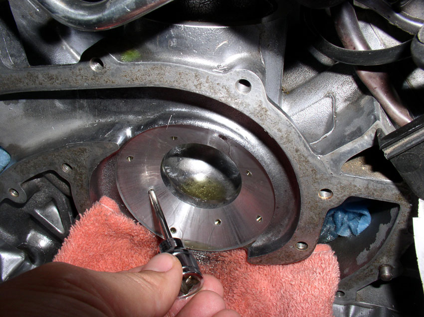
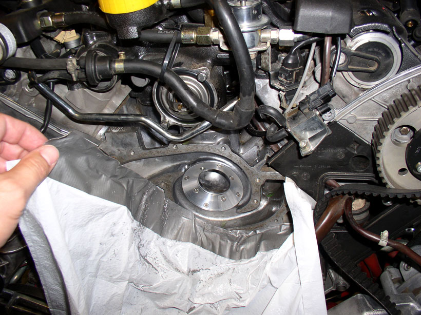
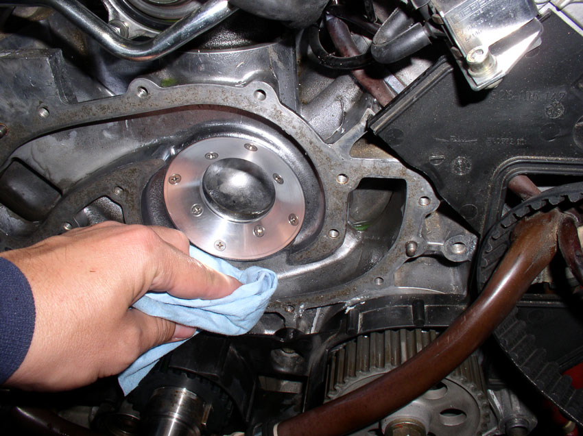
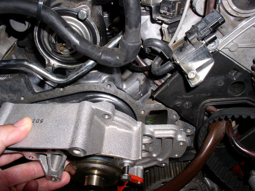
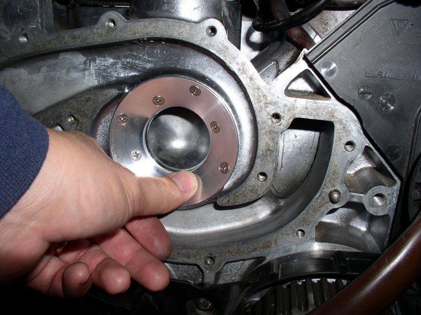
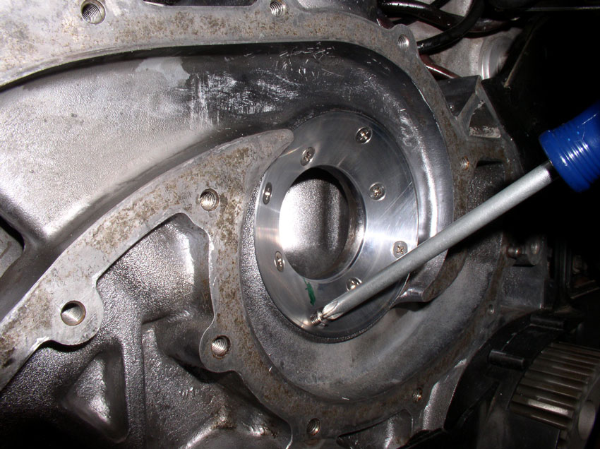
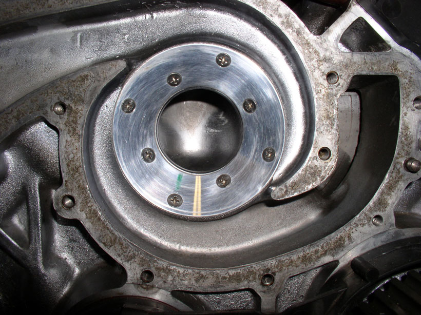
Next, I made sure the mating surface on the block was clean as possible and
removed any residual WP gasket material.
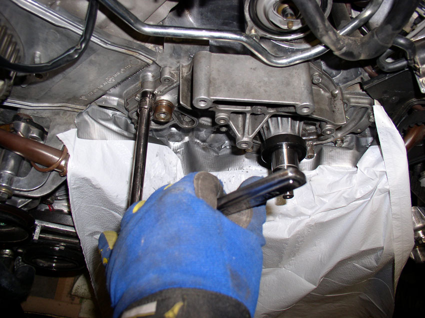
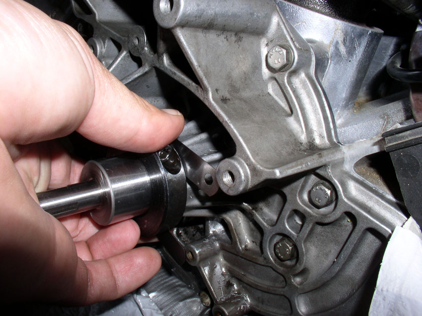
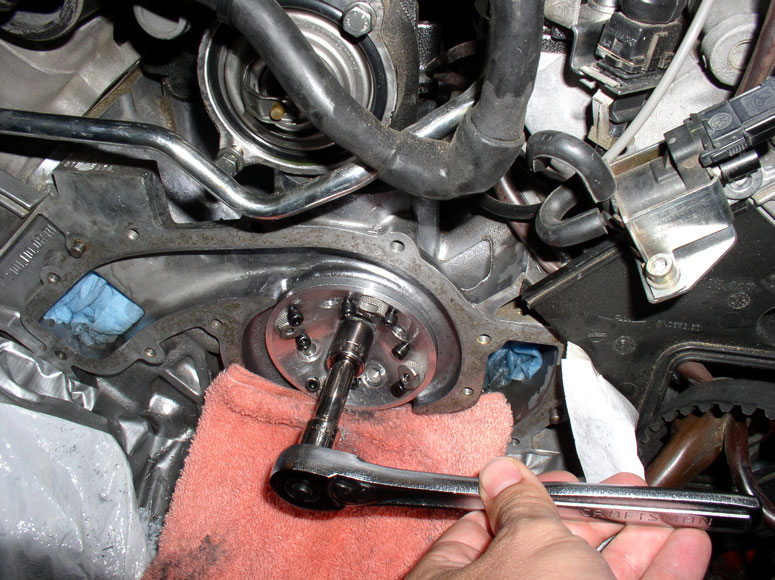
Then position the cutting tool into place.
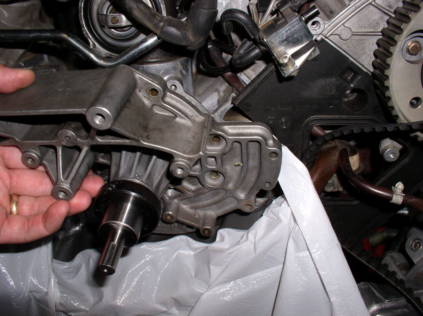
Since it's made from a WP casting, it has the locating holes for easy
placement.
Then I began installing the WP bolts to secure the cutting tool
According to the instructions, you will only need 5 or 6 bolts to hold the tool
in place. I tightened the bolts to factory spec for WP bolts - 7 ftlbs.
Continued.....
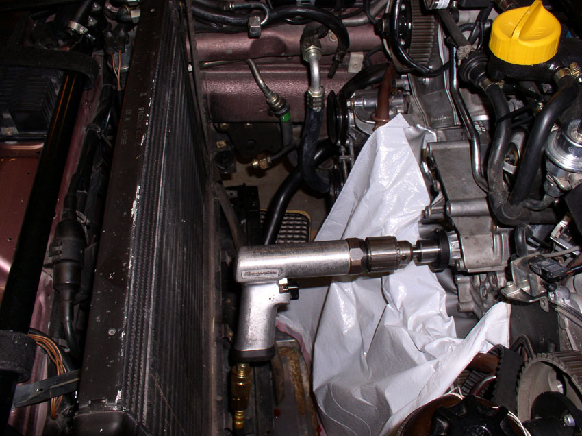
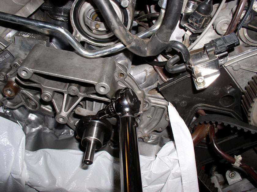
I did a test fit with the air drill just to see what type of
clearance I would be working with. Plenty of room to work with the radiator
removed.
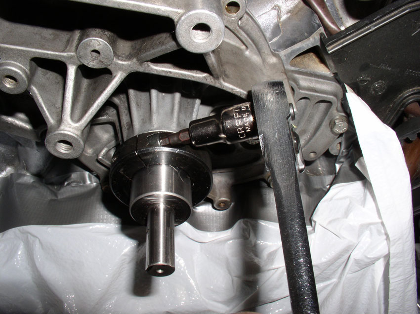
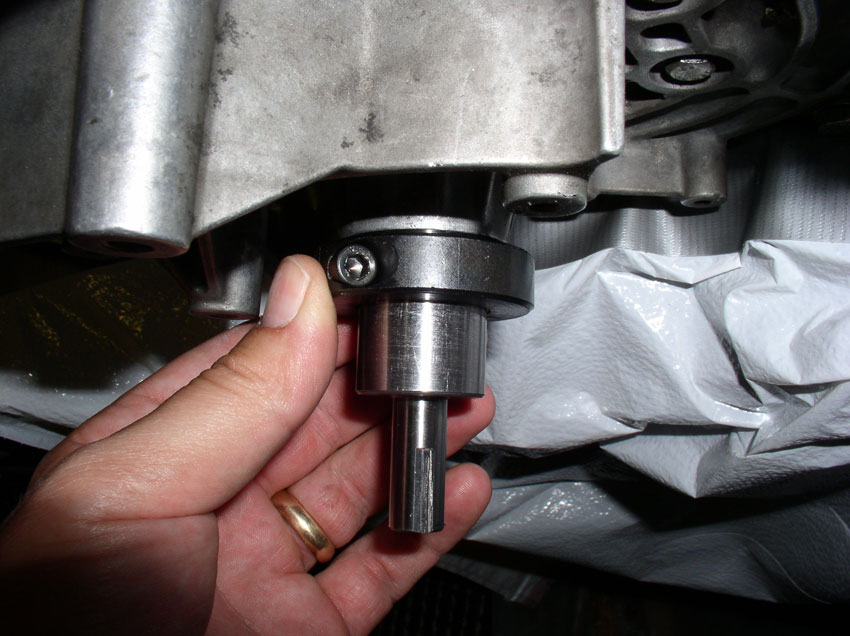
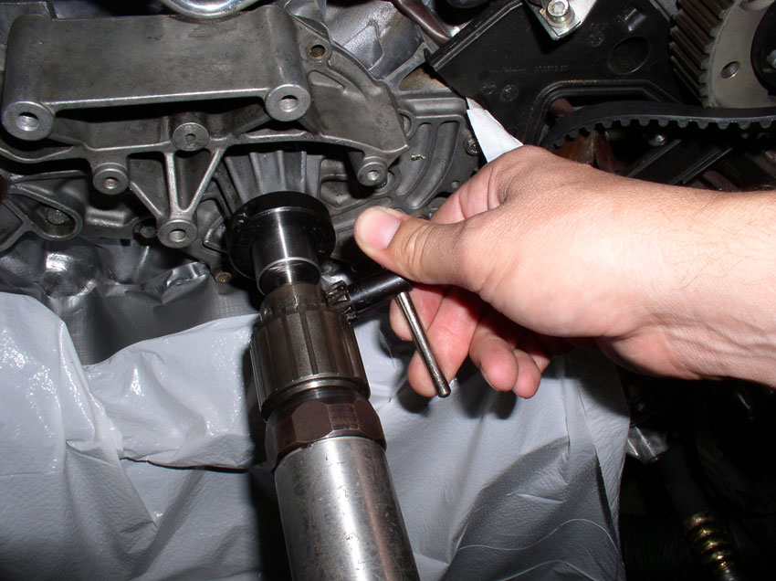
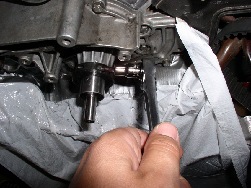
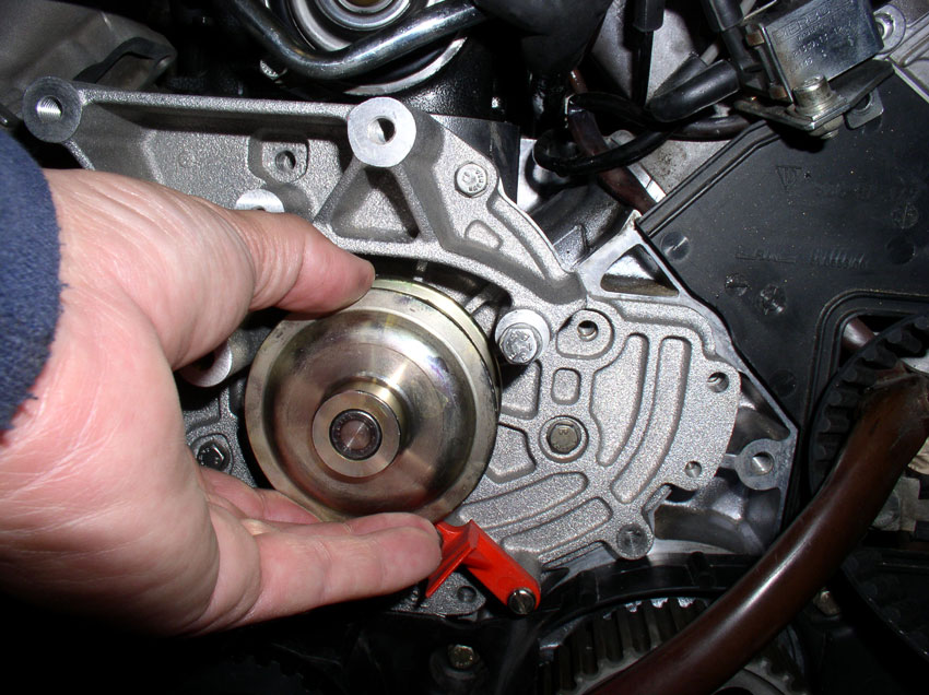
Next, the depth of cut needs to be set. Loosen the collar on the cutter shaft.
It uses an allen bolt.
In summary, the process goes something like this. Make an initial cut
(0.074"). Then check the cut surface to see if you got all the damaged
area cleared. If not, reattach the tool and set depth for an additional
0.010". Remove the tool and check to see if all damaged area has been
cleared. If not, repeat taking 0.010" depth of cut each time until the
damage is cleared. Inserts are supplied for each of these depths (e.g.,
0.084", 0.094", 0.104", etc.). The first cut is made to a depth
of 0.074". In order to get the depth set right, use feeler gauges in combination
to equal 0.074". Make up two stacks at this thickness.
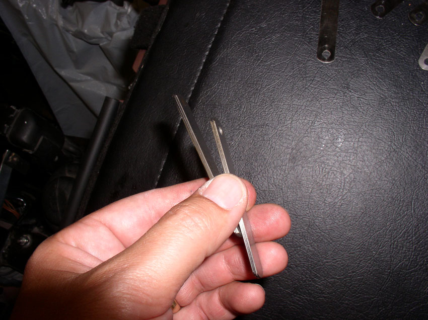
Then fit the feeler gauge stacks between the collar and WP casting as shown in
the picture below. Hold the collar against the feeler gauges to hold them in
place while tightening the allen
bolt. To get an accurate depth of cut, press and hold the end of the cutter
shaft against the block while holding the collar against the feeler gauges.
With everything held in place, tighten the locking collar in place. Greg
suggests a tightening torque but I don't remember what it is since I did not
keep a copy of the instructions - follow the torque recommendation in the instructions.
You will notice there should be a 0.074" gap now between the locking
collar and WP housing. This represents the amount of travel the cutter will be
allowed to cut.
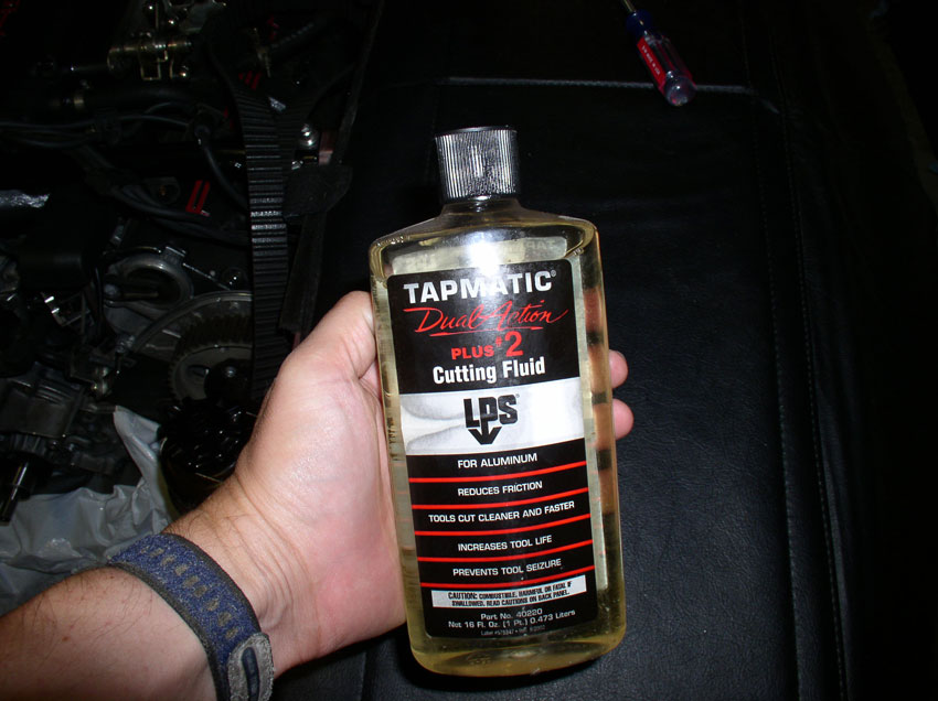
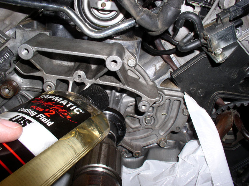
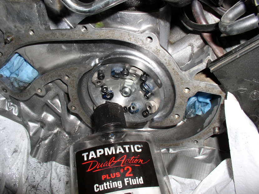
Greg also suggests you can use transmission fluid in place of cutting fluid.
However, I got my hands on some cutting fluid for aluminum on clearance very
cheap so I picked some up and here's what I used.
The air fitting on the air drill also used a 3/8" fitting and I only had
1/4" so I also picked up a 3/8" fitting kit....
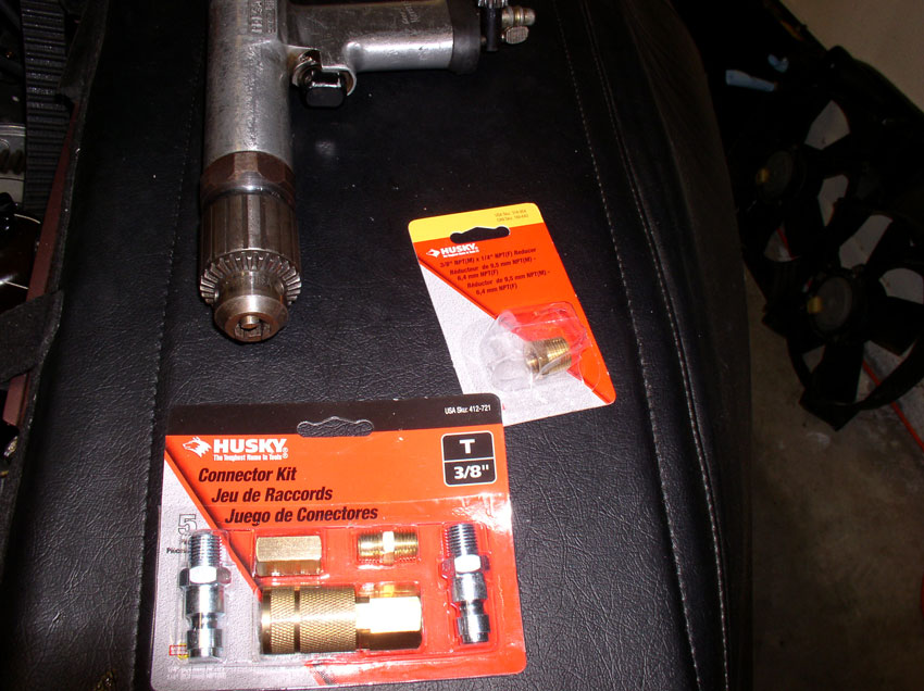
...and installed it with no problems.
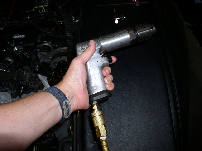
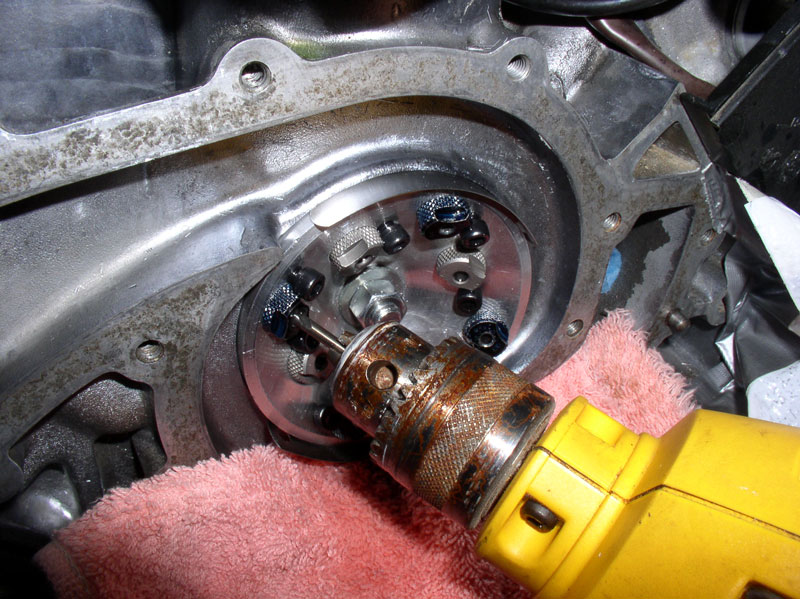
Next, I attached the air drill to the cutter shaft and tighted
down the chuck.
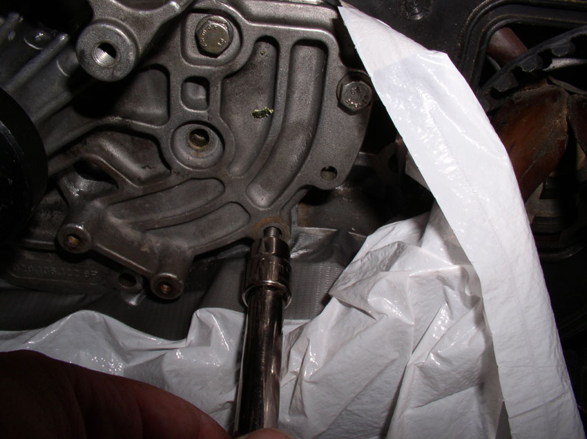
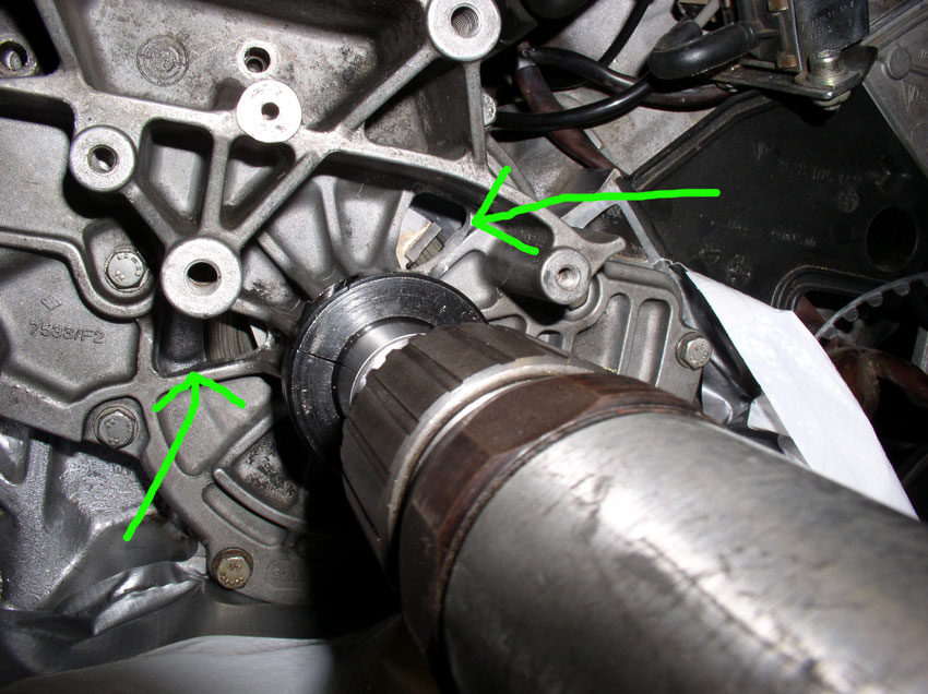
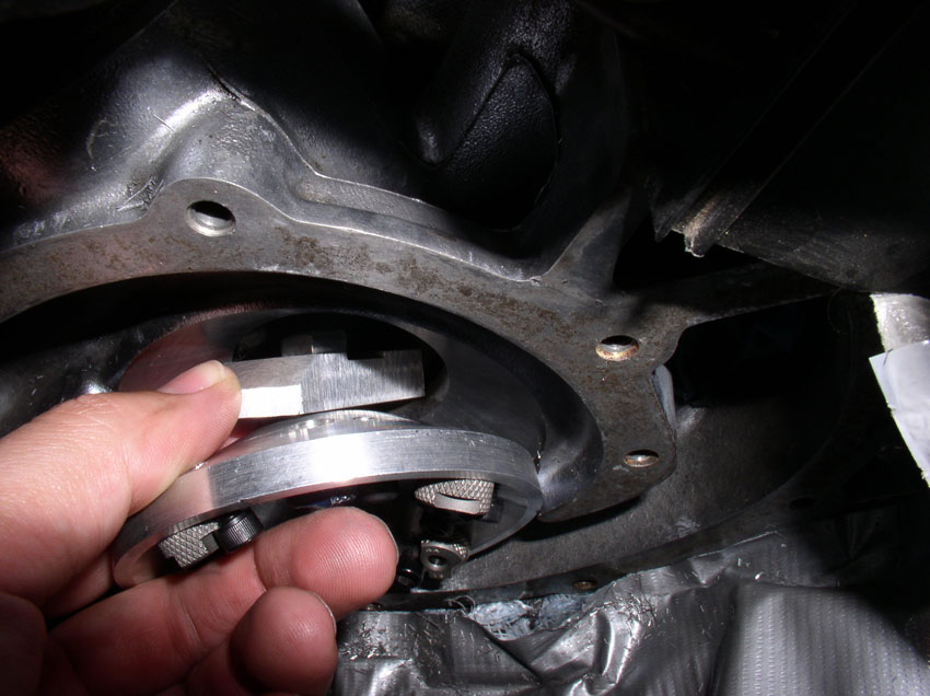
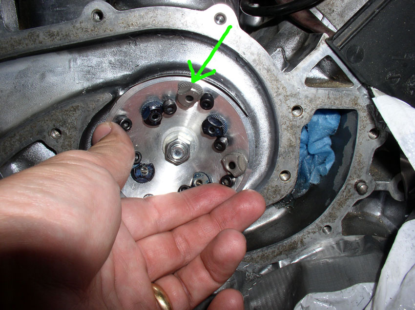
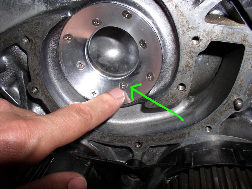
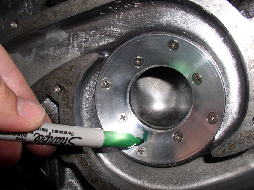
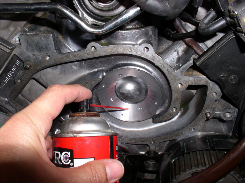
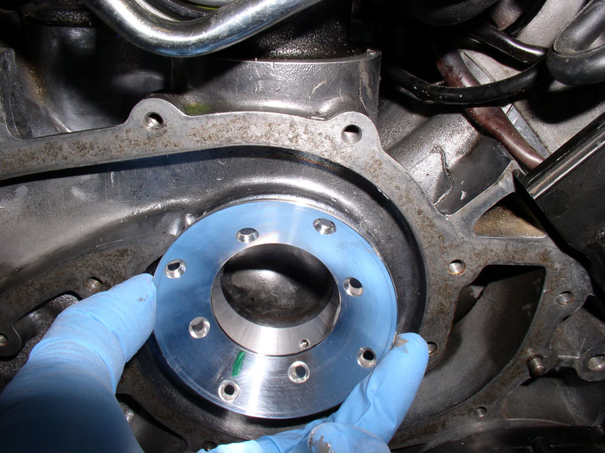
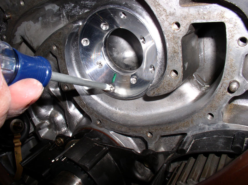
You will notice cut openings in the WP casting for shavings to escape. I used
these openings to squirt the cutting fluid since the bottle had a squirt-type
cap. There is also a hole in the top of the WP casting to adding cutting fluid
but I found these openings (indicated by the green arrows below) to be easier
to add the cutting fluid.
Next, I added the cutting fluid. I would add plenty of cutting fluid (since I
had a whole gallon of it) and added fuid between
stops and also added fluid while cutting.
Then I started cutting. I set the air pressure to about 90 PSI. It operates
pretty smoothly at first since the cutter is only making contact on a small
portion of the damaged area initally.
After a few moments, some filings start to appear from the removed material.
Greg's instructions are very good at detailing what to expect from the drill
performance (chatter) and amount of filings to expect as you continue to drill.
At first, small filings will appear since the edges of the damaged area are
being addressed by the cutter first. Then, the filings get longer as you cut
and clear larger, wider areas.
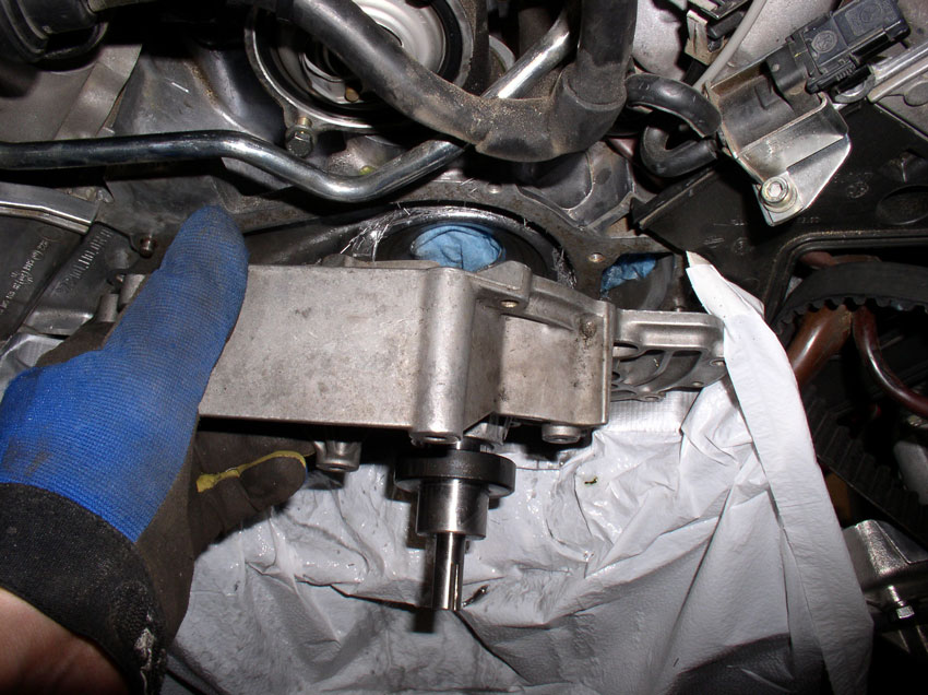
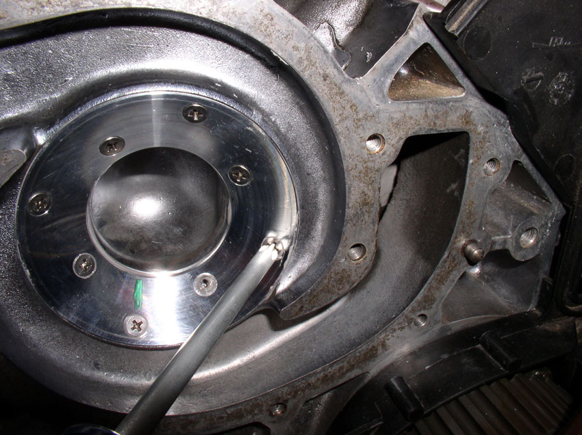
Drill until the locking collar meets the WP casting. At this point, the cutter
will turn fairly easily as it has removed all the material allowed by the
locking collar. Disconnect the drill from the cutter shaft and remove the
WP-to-Block bolts....
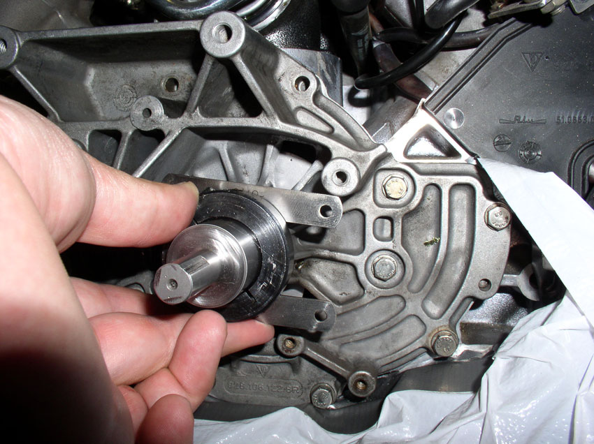
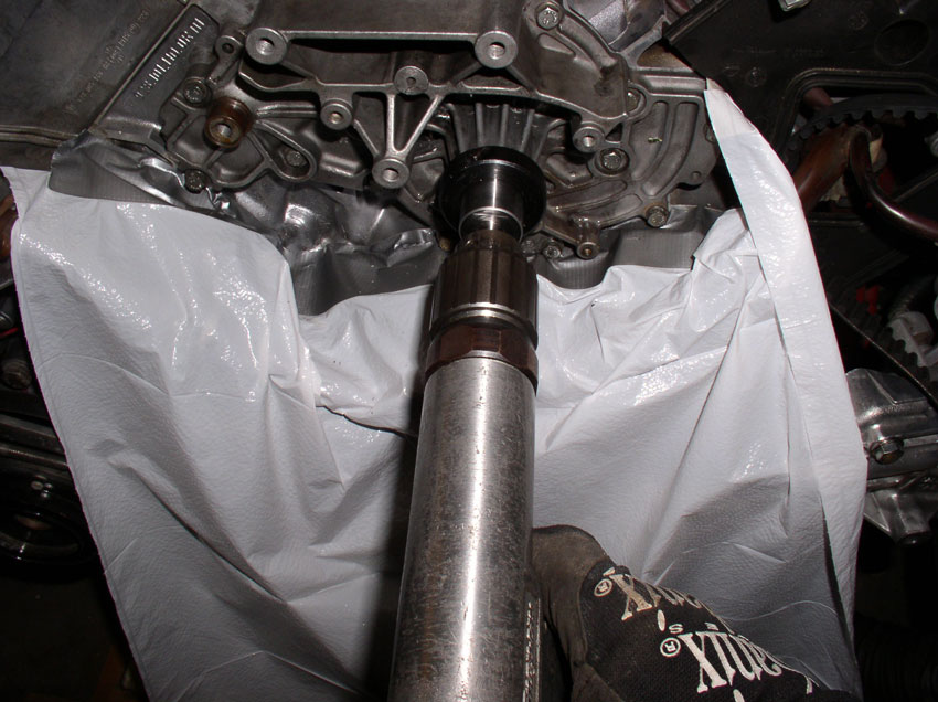
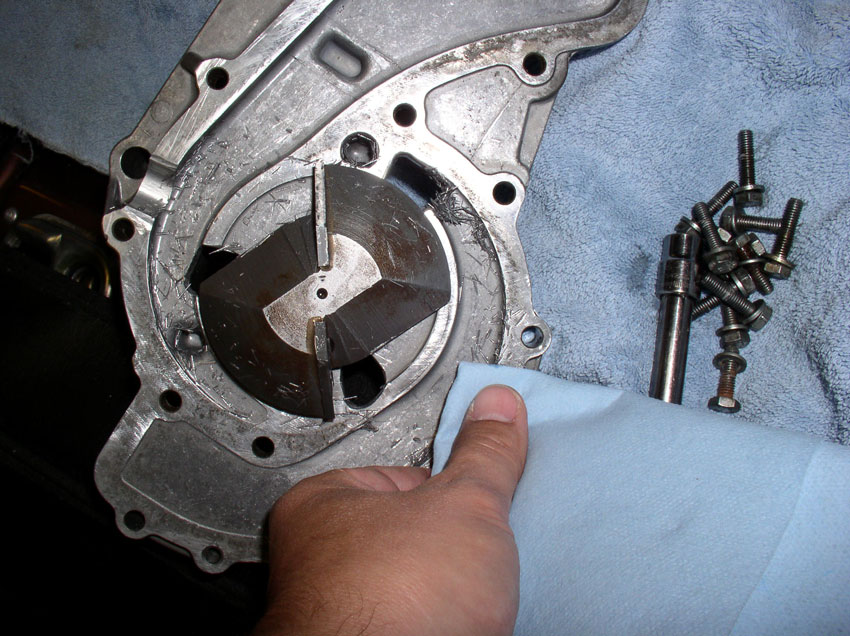
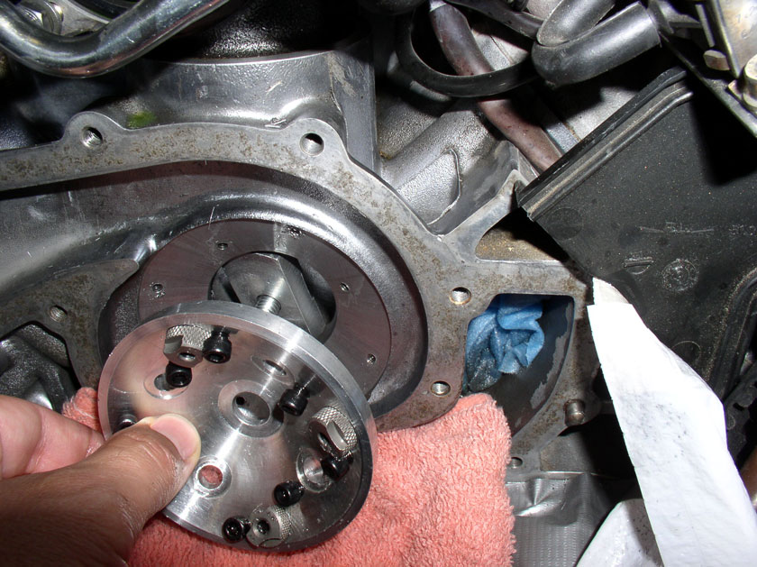
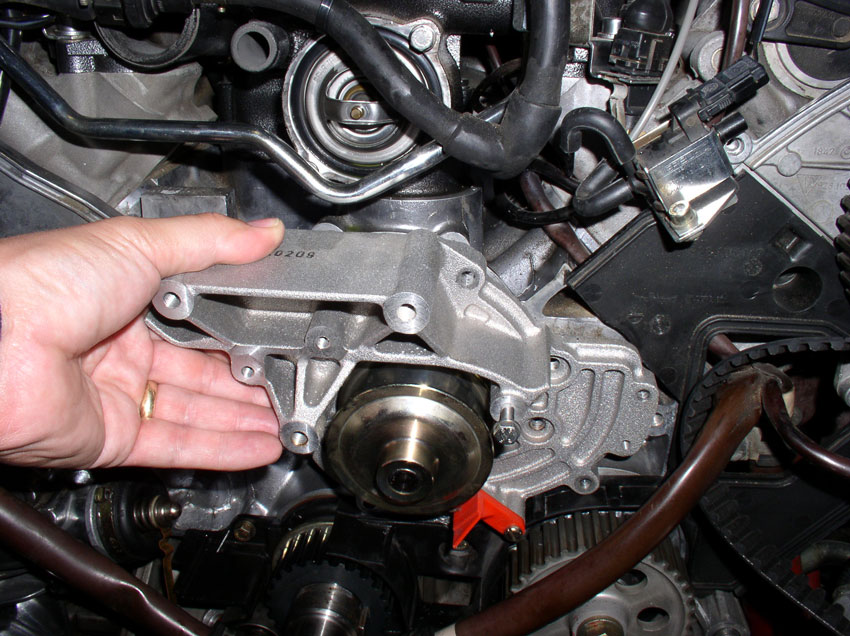
...and remove the cutting tool from the block.
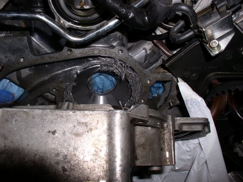
Flipping over the cutting tool, you will see some of the filings from the cut.
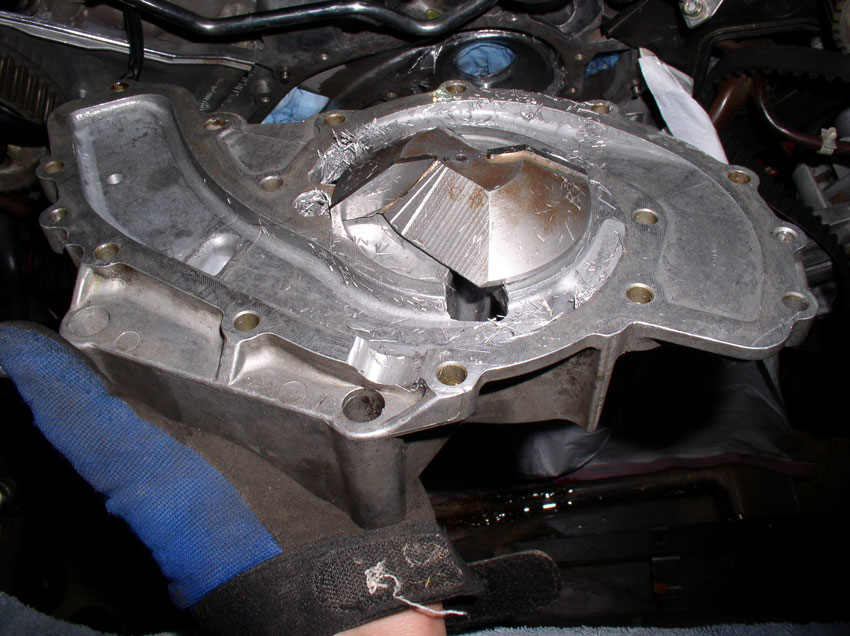
And the same thing on the block.
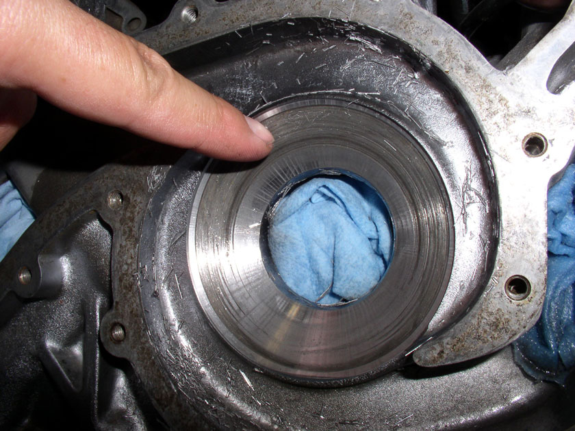
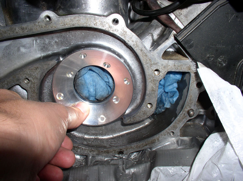
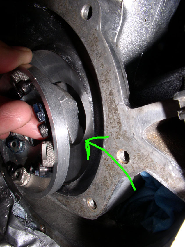
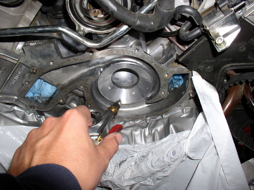
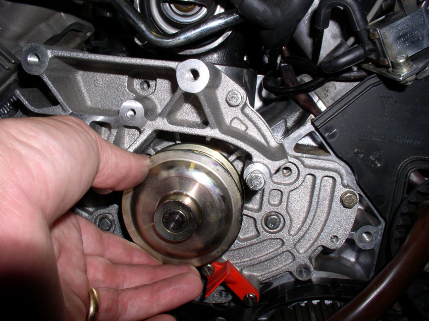
Closer inpsection of the block shows that there is
still damaged block area that needs to be cleared after just 0.074" have
been cut. I will need to cut an additional 0.010".
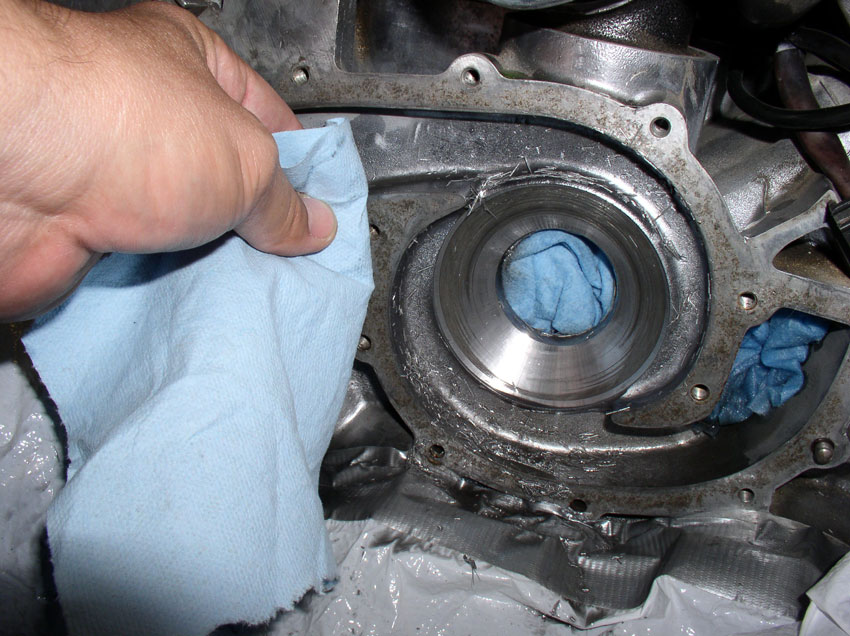
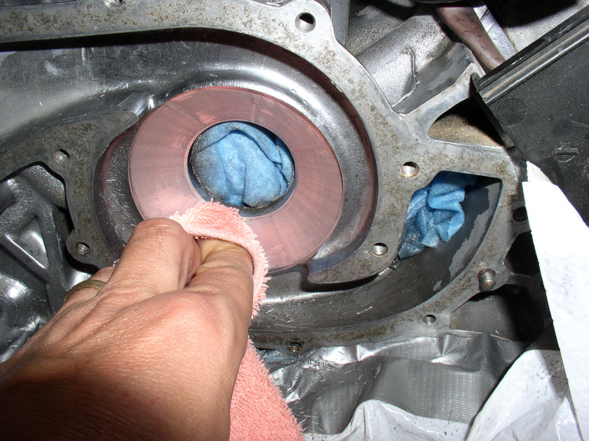
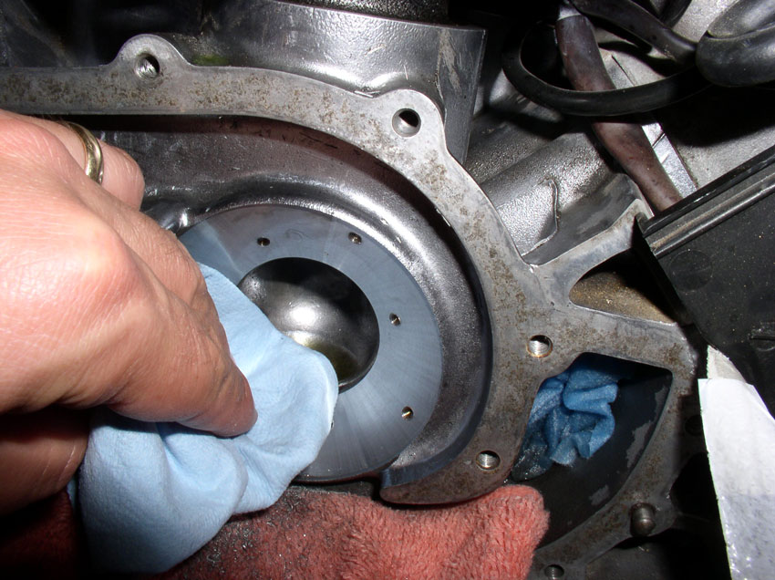
To prepare the tool and block for another cut, clean all the filiings from the mating surface on the block. You will
want to have an acurate measure of cutting depth and
making sure there are no filiings between the block
and cutting tool housing helps ensure accurate cuts.
Also clean the mating surface on the cutting tool.
Then, reattach the cutter to the block with the WP-to-block bolts.
You will need to loosen the locking collar allen head bolt in order to reset the depth of cut.
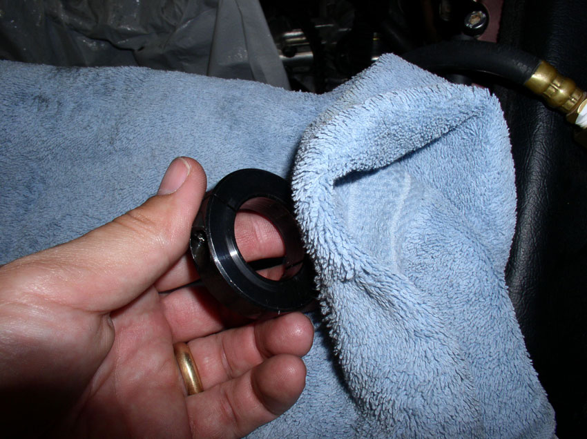
However, I went ahead and removed the locking collar from the cutting shaft as
it seemed like a good idea to also clean off any filiings
that may have logded between the locking collar and
WP casting. Again, a precaution I took to help ensure accurate cut depths.
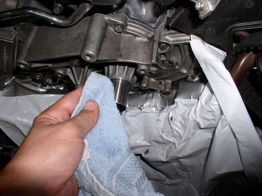
With the locking collar off, I also cleaned the cutter shaft and WP casting
where the locking collar rests.
Next, set the depth of cut to 0.010" by again selecting feeler gauges that
total this thickness and place them between the locking collar and WP casting
as before - holding the cutter shaft against the block and locking collar
against the WP casting.....
....then tightening the allen
head bolt to the specified torque.
Now attach the drill again as before, tighen the
drill chuck and drill while applying cutting fluid. This time, more material
was being removed and the drill/cutter gave considerable chatter feedback.
However, with a little practice, you can vary the pressure to minimize the
chatter. After you have reached the cutting depth and the drill/cutter operate
smoothly - indicating a smooth surface has been cut - you can remove the drill
and remove the cutting device as before.
Once you take off the cutting tool, you will notice the filings are longer and
there are many more of them.
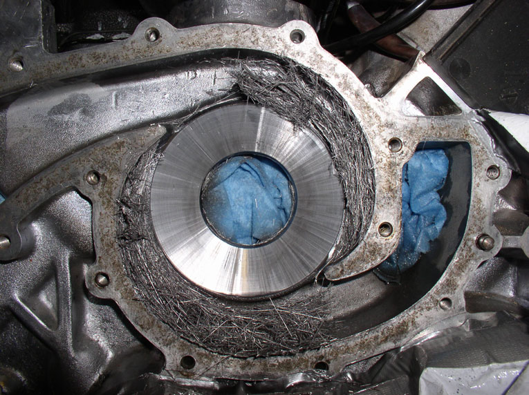
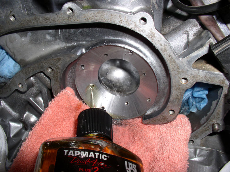
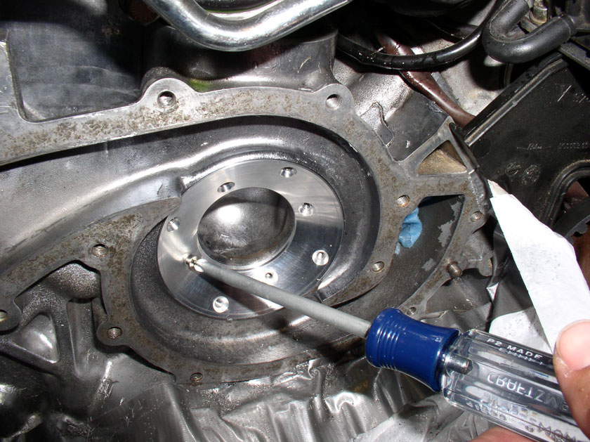
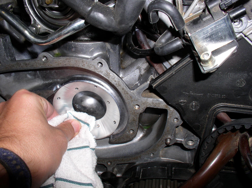
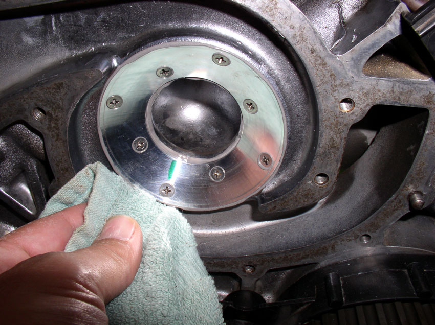
Clean the surrounding area of filiings. For mine, the
extra 0.010" did the trick - removed the remaining damaged area in the
block. I moved my fingers across the surface and it felt smooth with barely
perceptible imperfections.
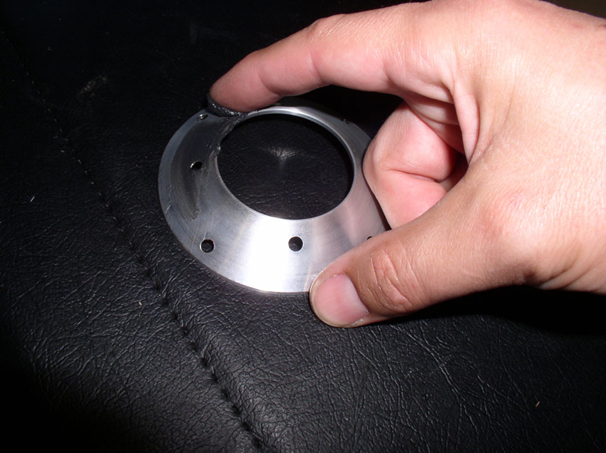
Next, it was time to try a fit check with the corresponding insert for
0.084" (0.074" initial cut + 0.010" for the second cut).
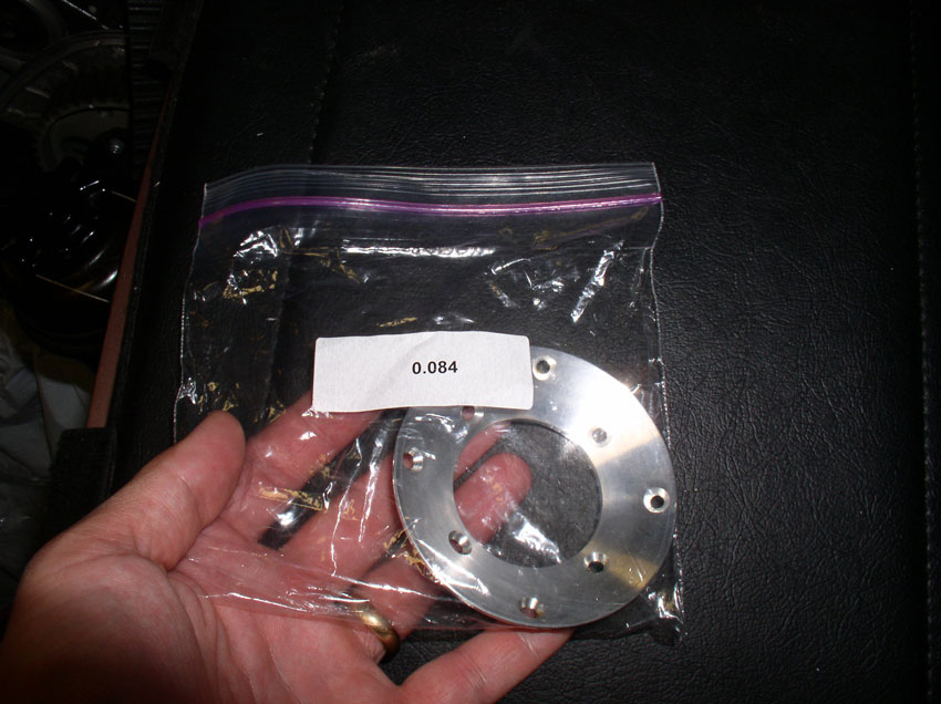
Initially, I tried the insert on dry just to see how it fit. It fit very
nicely!
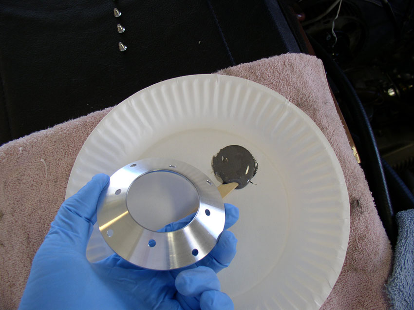
Next, Greg's instructions suggest putting a small amount of grease on the back
of the insert to help it stay in place on the block while performing a fit
check with the water pump. I applied a small amount of grease to the back of
the insert.
Then place the insert onto the newly machined block and confirm it is correctly
seated and stays in place.
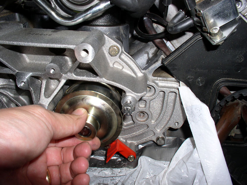
Next, install the water pump without gasket. According to the instructions,
when you apply the JB weld under the insert, it raises the insert outward.
However, adding the WP gasket also moves the impeller outward. As long as the
WP doesn't scrape here, it shouldn't scrape when applying the JB Weld and WP
gasket.
Then, tighten the WP down with the WP-to-block bolts. I went ahead and
installed all the bolts to ensure I had a good fit with no scraping.
Next, turn the WP Belt pulley - I tried it both forwards and backwards. Also
try lifting up from under the pulley while turning to simulate the force the
belt will exert on the pulley. Both resulted in no scraping.
Remove the WP-to-block bolts and remove the water pump from the block. Then
remove the insert.
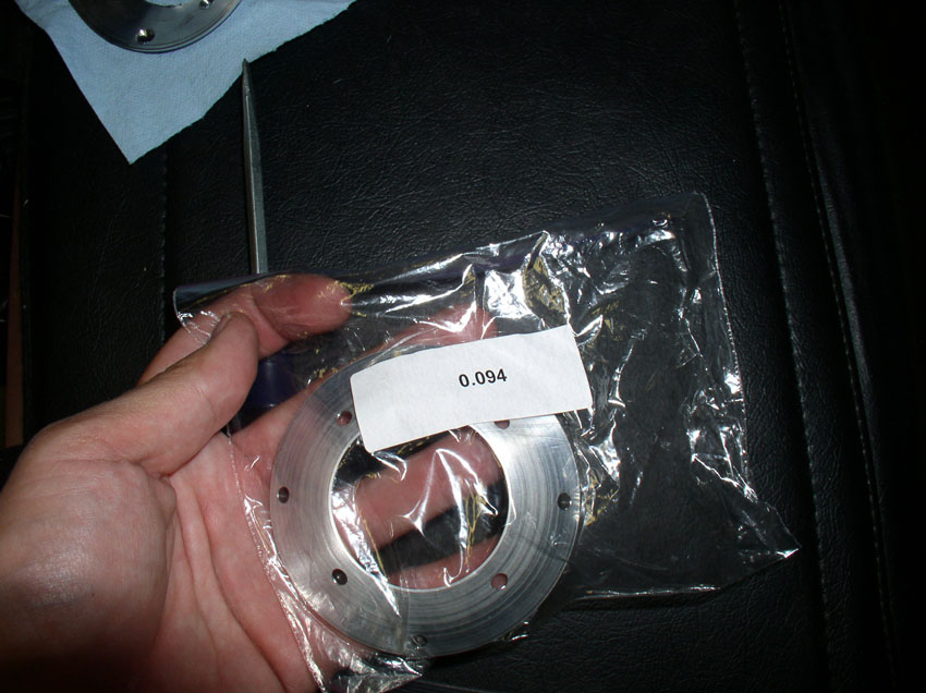
To ensure we don't have too big of a gap between the insert and the impeller
and to confirm we have the right sized insert used, try fitting the next size
insert up (i.e., 0.094" in my case).
Re-install the water pump and bolts and check the TB pulley for scraping. On
mine, the impeller was scraping when I had the 0.094" insert installed.
This confirmed the 0.084" insert was the right size. IF there was no
scraping when I installed the 0.094" insert, I would keep installing the
next larger insert until I felt/heard scraping from the impeller then I'd go
back to the last insert that worked without scraping and use that one for the
install - according to the instructions.
Remove the water pump once again as well as the insert and clean the surfaces
of the block and insert to remove the grease.
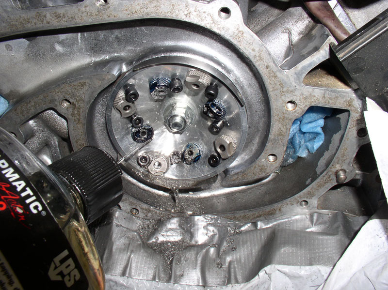
Next, I removed the stuffing from the center water port in preparation for
installing the drilling/taping jig.
Clean the mating surface on the block and the inside of the center coolant
port.
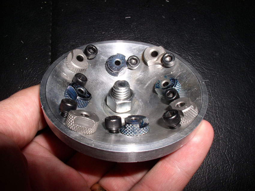
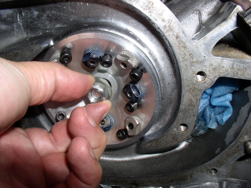
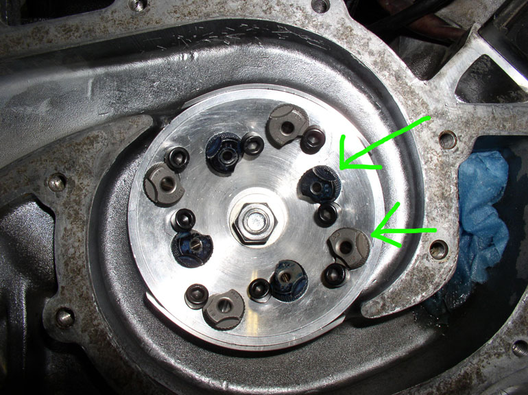
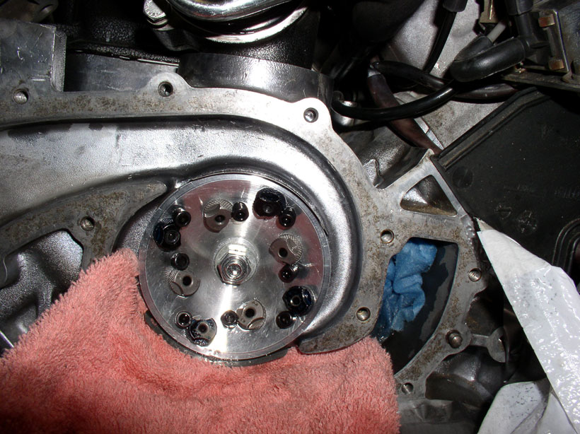
Here's the drilling/tapping jig. You will notice 8 inserts all around. Four of them toward the outer edge (silver colored ones in the pic below) and the other 4 toward the inner edge (blue in
the pic below). Each insert is held in place
by a small allen head bolt.
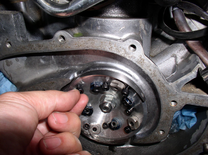
According to the instructions, the blue inserts are for drilling and the silver
inserts are for tapping. The jig is set up for drilling the inner 4 holes
first.
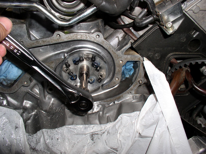
The jig is held in place with a block to the rear that is attached to the jig
with a bolt that goes through the center of the jig as pictured below. Orient
the jig as shown for installation into the center coolant port.
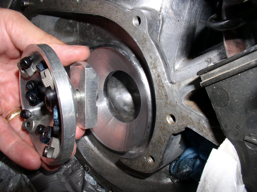
Since installing the jig is a little tricky, unscrew the bolt as far as you can
without removing the bolt. Then angle the square end of the block down into the
coolant port as shown.
Slide the block down far enough for the top rounded end of the block to clear
the top of the coolant port as shown in the pic
below.
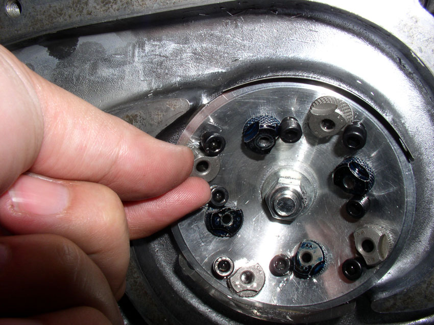
Next, tighten up the nut on the front of the jig as shown. However, don't
tighten it down because it will need to be "clocked" to the correct
position before drilling.
With the nut still a little loose, install a couple of feeler gauges to help
center the jig in the coolant port. You can use two gauges each about
0.008" or 0.009" thick. I used one 0.008" and one 0.009".

Insert the gauges one above and one below as shown in the pic
below. The fit will be tight enough to hold the feeler gauges in place while
allowing you to clock the jig into the correct position.
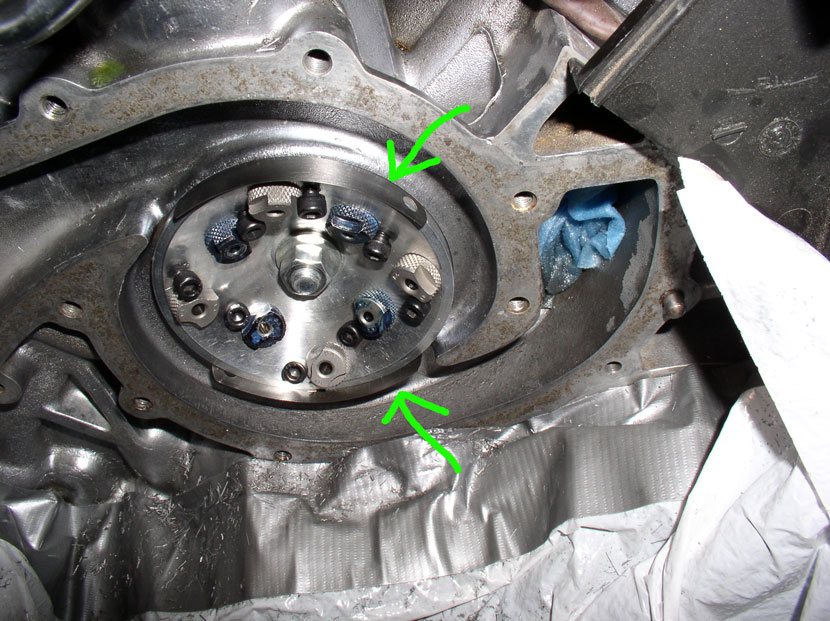
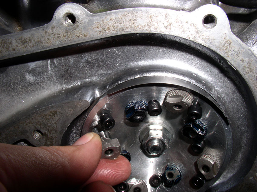
Next, clock the jig so the top outer insert (silver) is in the approximate
According to the instructions, the likely candidate to punching through is the
insert located at the
Next, tighten down the bolt that holds the jig in place. It doesn't require a
lot of force - I just snugged it down.
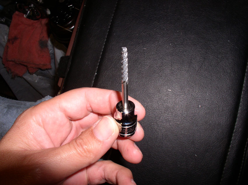
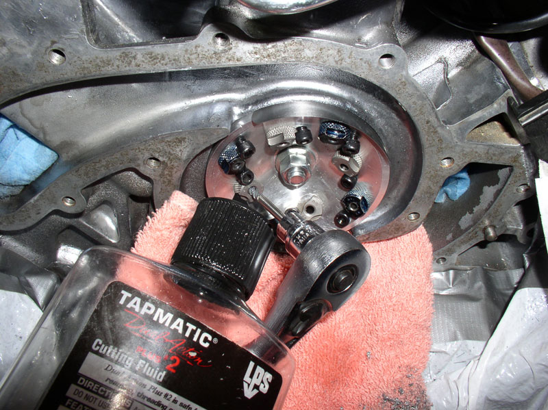
Drill the blue inner inserts first using the supplied drill bits. There are
extra drill bits in case the one you start with gets dull. I was able to drill
all 8 holes with a single drill bit. The instructions recommend keeping the
used drill bit so it does not get mixed with the others and does not get passed
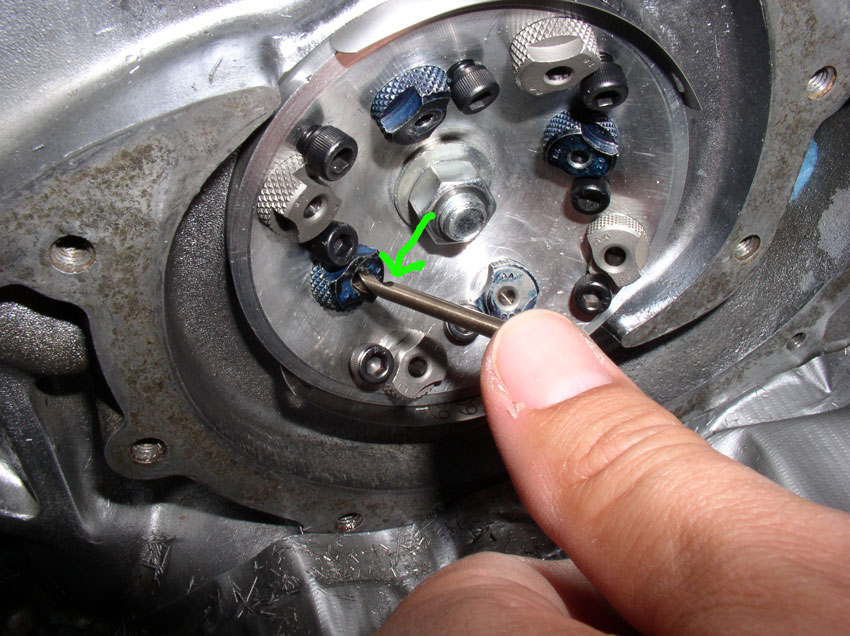
along to the next user. I test fit the drill bit into the insert to see how
deep I would be drilling. The instructions explain to drill down to the top of
the cutting flutes of the drill bit (see green arrow in the pic
below).
I applied cutting fluid by squirting it into the insert to be drilled....
Then began drilling with slow steady pressure but not too
much pressure. It is also best to position the drill bit all the way
into the insert before starting to drill as this will preserve the sharpness of
the drill bit. This seemed to work well for preserving the drill bit I was
using.
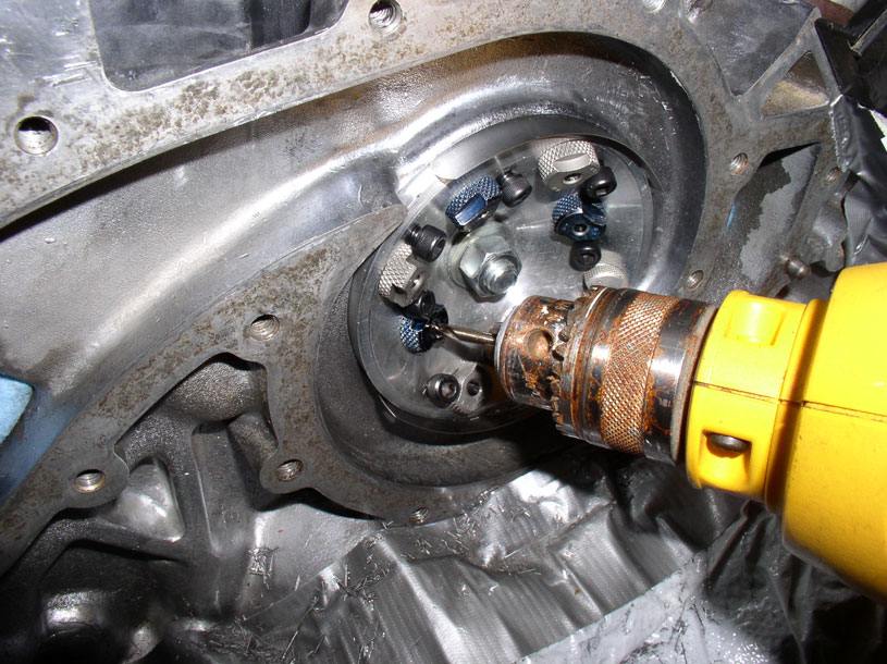
Drill down to the top of the drill bit flutes as shown.
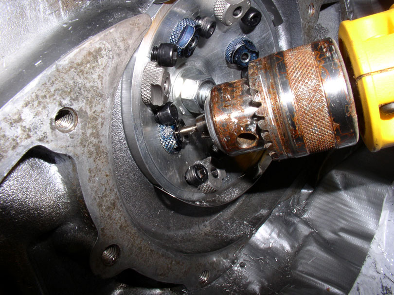
I continued in a clockwise fashion to drill the remaining 3 holes (i.e., dark
blue inserts).
After the initial drilling is done, I flushed the filiings
out with cutting fluid
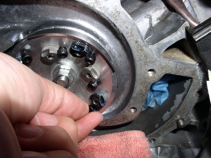
Now the drilling inserts need to be relocated to the outer edge of the jig. I
began by removing the outer tapping inserts. You loosen the hold down allen head bolt as shown below.
Then rotate the insert counter clockwise as shown....
...and pull out the insert.
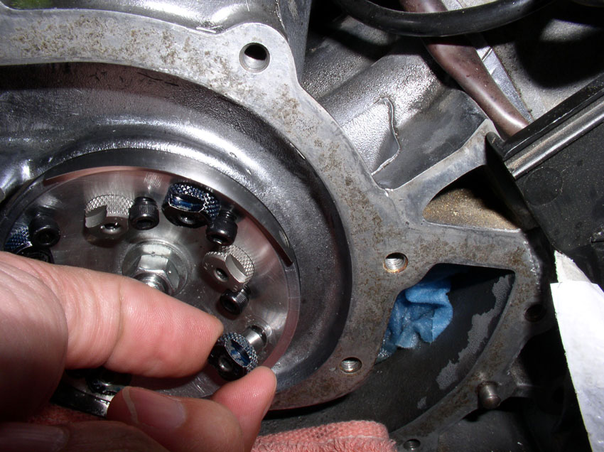
Remove all the inserts in this manner leaving the hold down allen head bolts.
Then reinstall the dark blue drilling inserts in the outer holes. Install the
inserts until seated and turn clockwise.
Then hand tighten the allen
head bolt to hold the insert in place.
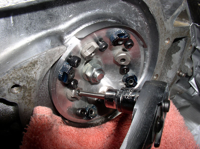
When the jig is reconfigured, it should look like this.
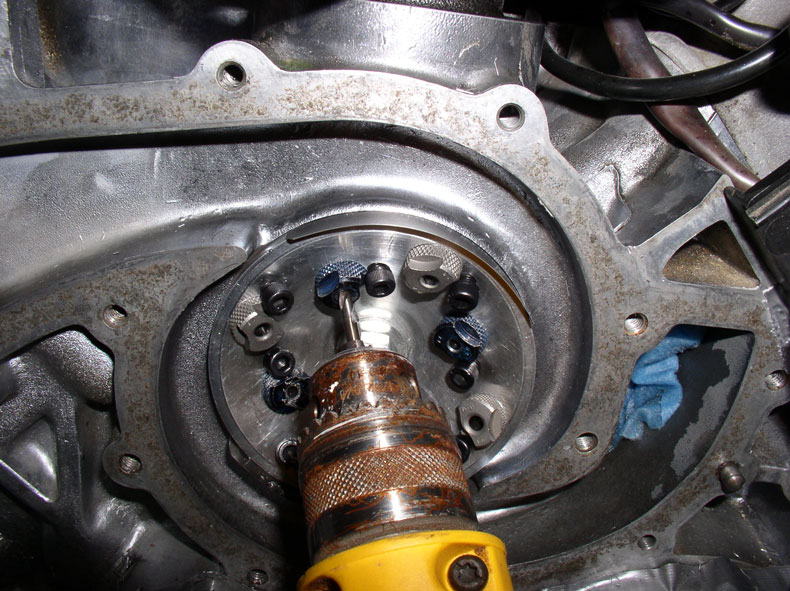
Then, resume drilling the outer inserts as shown.
After drilling, flush with the cutting fluid again and prepare to begin the
initial tapping.
Here's the tapping bit. I was lucky enough to have a 3/8" socket adapter
that the tap would fit into (the kit does not come with the socket adapter). I
used this to begin tapping.
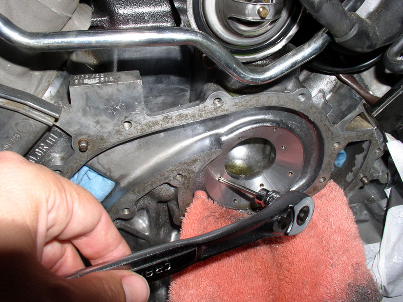
You will begin tapping using the silver colored inserts. I attached the tap to
the 3/8" socket wrench and fitted the tap into the insert.
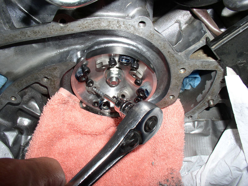
Use cutting fluid during the tapping.
Carefully tap the hole using the wrench until you feel slight resistance from
the tap bottoming out in the hole. You can also judge approximately when you
are getting close to the bottom of the hole by comparing the distrance travelled to the same
distance travelled when drilling the hole with the
drill bit.
After tapping all 4 of the inner holes, you will need to reconfigure the
drilling/tapping jig for tapping the outer holes. First, loosen the allen head bolts on the dark blue inserts....
...and remove the 4 outer dark blue inserts.
Then, install the silver tapping inserts in the outer holes.
The jig should look this this when reconfigured - no
need to reinstall the dark blue inserts into the inner holes since we won't be
using them any more. Leave the blue inserts out for cleaning.
Next, begin tapping the outer holes in the same manner you tapped the inner
holes.
When all 4 of the outer holes have been tapped, you can begin removing the jig
and prepare for the final tapping. First, remove the feeler gauges.
Then, loosen the securing bolt for the jig.
Remove the nut all the way from the bolt, this will
ease removel of the jig from the block.
Flush the newly tapped holes wth cutting fluid.
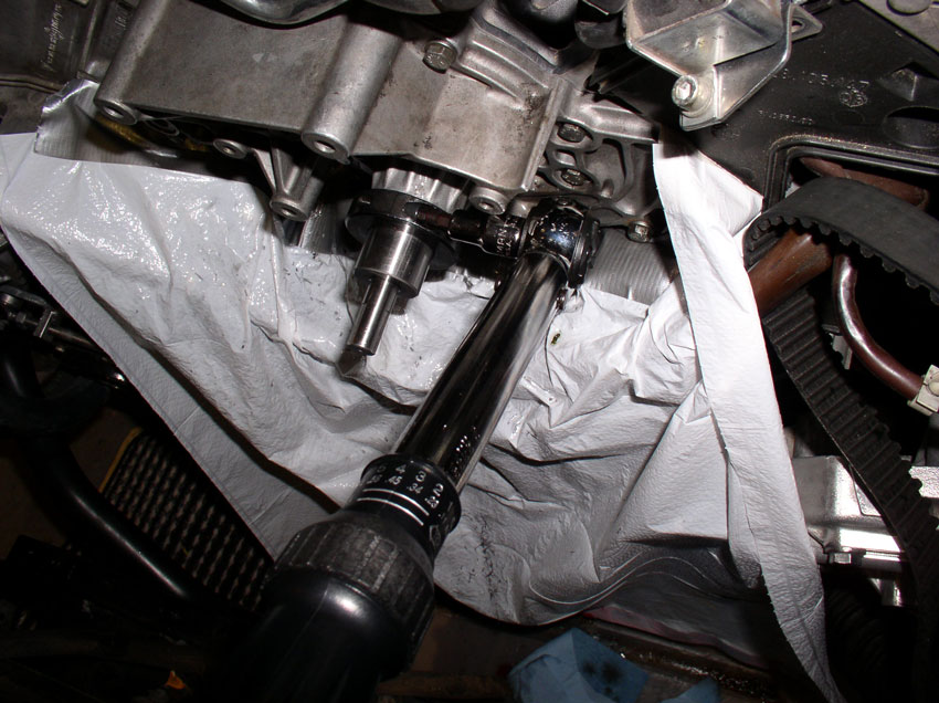
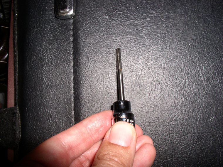
Here's the final tapping bit. I also fitted it into my 3/8" socket
adapter.
Performing the final tapping can be tricky in that you don't want to cross
thread the holes you just tapped with the jig. I simply started the tap by
hand, as shown below, by carefully wiggling and turning the tap to get it
started in the hole.
Then attached the socket and began tapping the hole. Again,
being careful to sense when the tap bottoms out without applying additional
force.
When completed with tapping all 8 holes, flush with the cutting fluid and wipe
up excess fluid.
Then I used brake cleaning fluid to dissolve/clean any cutting fluid residue
from the holes and repaired surface area.
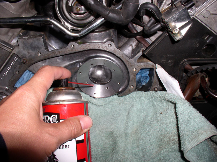
I then blew out any remaining brake fluid with compressed air.
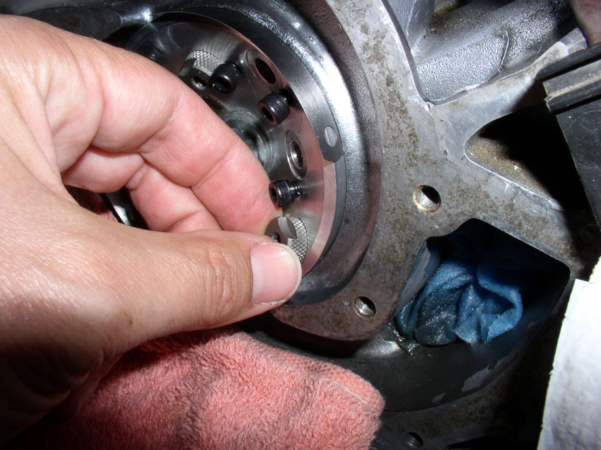
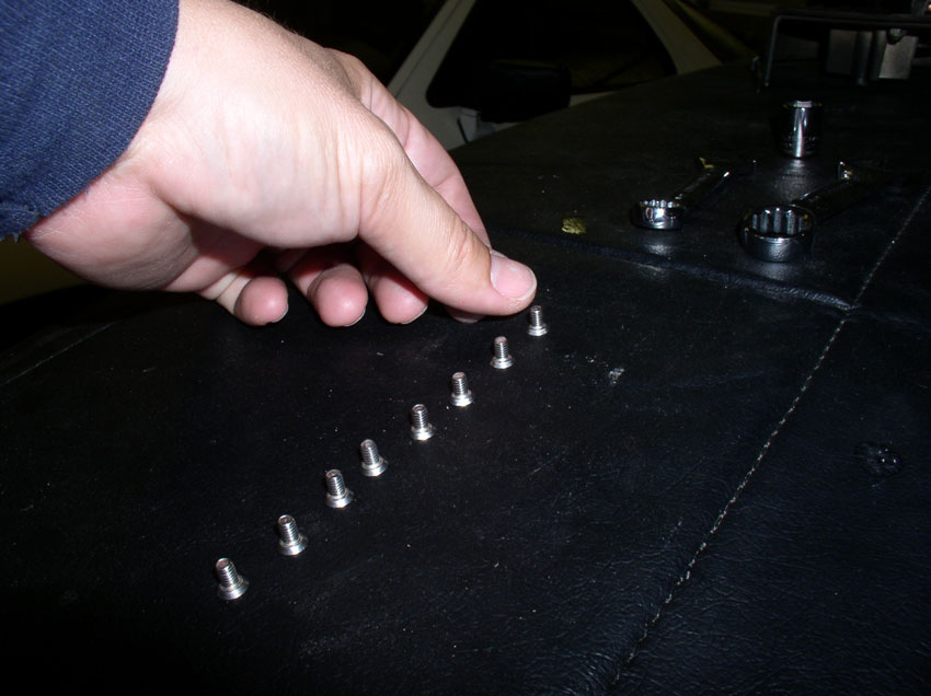
Next, I needed to do another dry fit check with the screws attached to the
insert/block. Verify the insert holes line up with the 8 holes you just
drilled/tapped then install one screw to hold the insert in place. There are
plenty of screws supplied with the kit.
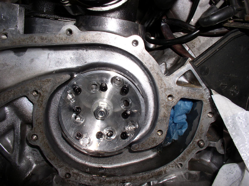
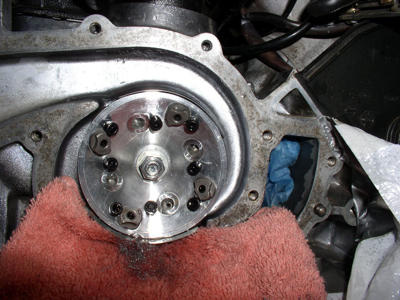
Install all 8 screws into the insert.
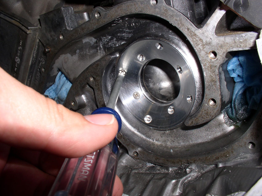
Then, run your fingers over the tops of the screws to make sure they are all
below the surface of the insert (or at least flush with it). There should be no
screws sitting above the surface of the insert.
Since I was done drilling/tapping, I began some clean up. Removed
the left coolant port plug/towel.
...and the right one.
Removed the plastic sheeting for deflecting cutting fluid
runoff.
Wiped all the surfaces in and around the water pump down.
Used a shop vacuum to pick up any stray filings.
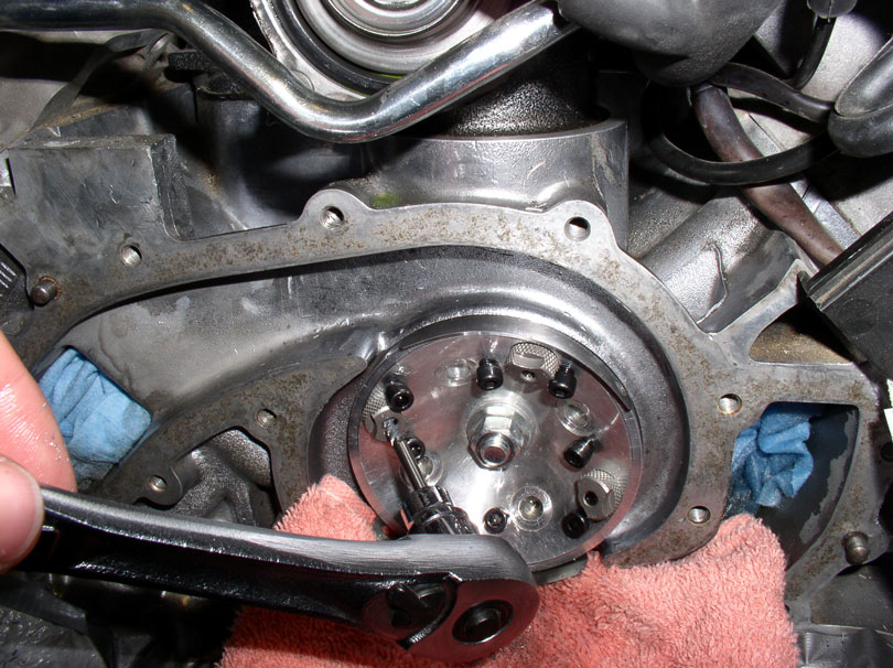
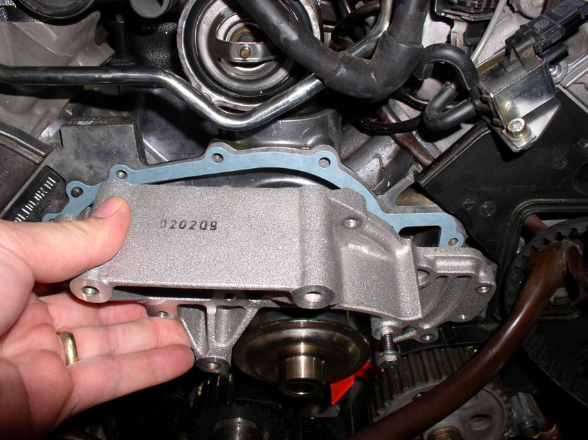
Installed the water pump without gasket....
...and tightened 5-6 bolts to secure the pump to the block. Then
turned the TB pulley to check for clearance of the screw heads.
Unfortunately, I was hearing and feeling at least one screw head hitting on the
impeller blades.
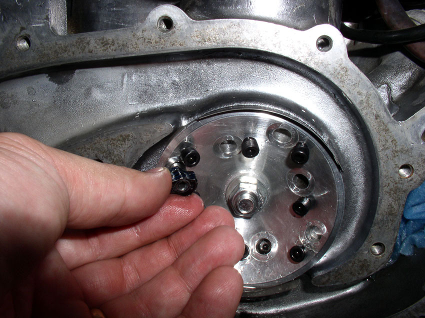
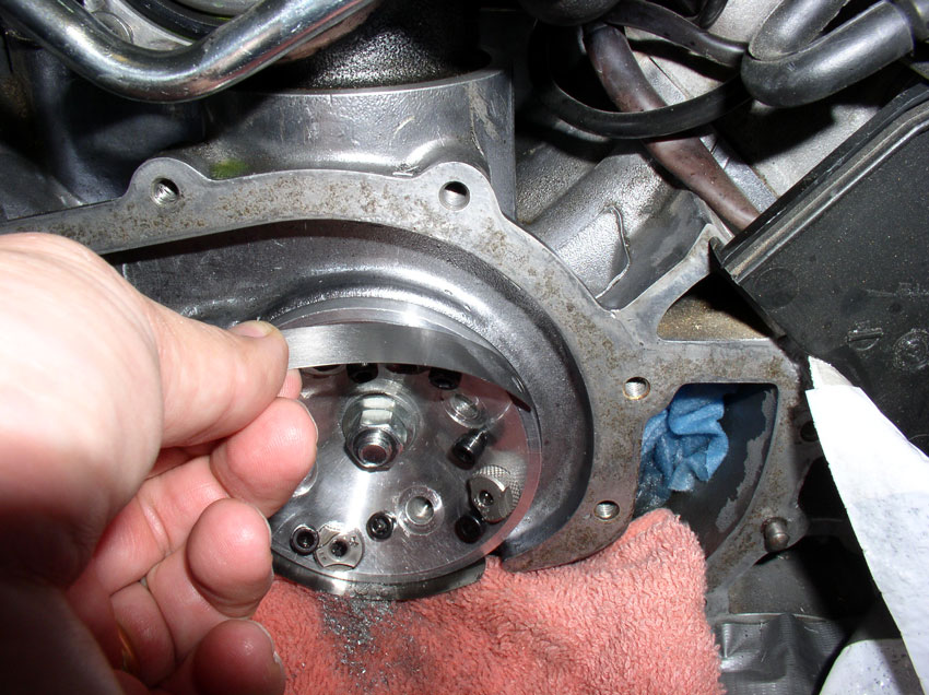
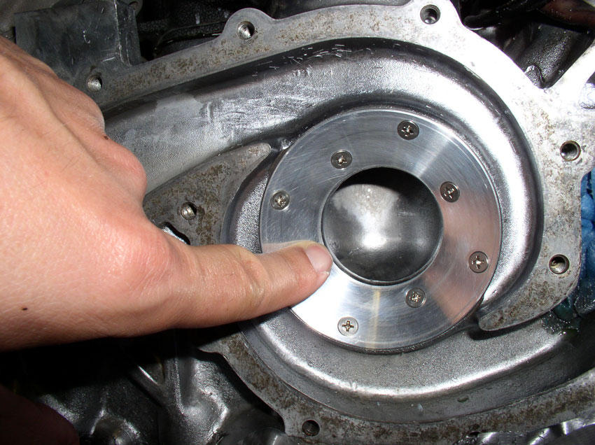
I removed the water pump and ran my fingers across the screw heads again. This
screw felt a little high (see green arrow below).
I replaced the screw with another one from the kit that seemed to fit much
better. There are small variances in manufacture of the screws and some have
thicker head rims than others. By trying different screws and feeling the
surface, I found one that fit. The kit also comes with countersink drill bits
that you can use to further counter sink the holes in the insert but I was
fortunate enough to simply find different screws that fit better than others. I
repeated this test and replace screws cycle a few times until I ended up
replacing about 3 screws.
After replacing any "high" screws, replace
the water pump and secure it to the block as before to test again.
Turn the TB pulley and listen for any scraping sounds. Also try applying upward
pressure while turning the pulley to simulate the pressure the TB will apply to
the pulley. At this point, I could feel no more scraping from the screw heads.
Now, you are ready to apply the JB Weld and install the insert permanently.
First, since each screw is matched with each hole, mark one of the screw holes
on the insert with a marker as shown. You will want to reinstall the screws in
the same holes you remove them from.
Then remove the screws starting at the location you just marked. I moved
clockwise from the marking on the insert. Make note of which hole in the block
the marking is located.
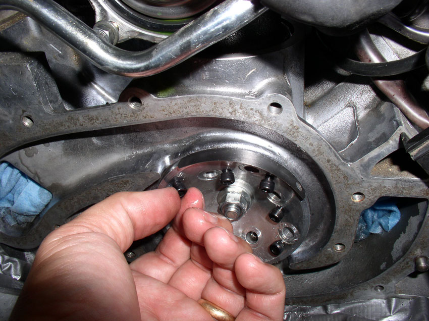
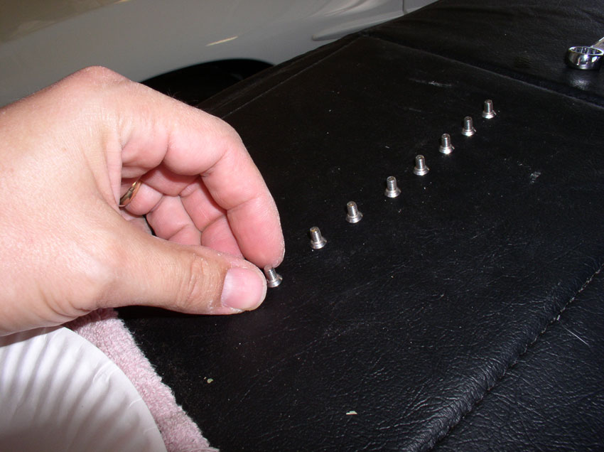
Line up the screws in the order removed.

Remove all 8 screws in this manner keeping them in order.
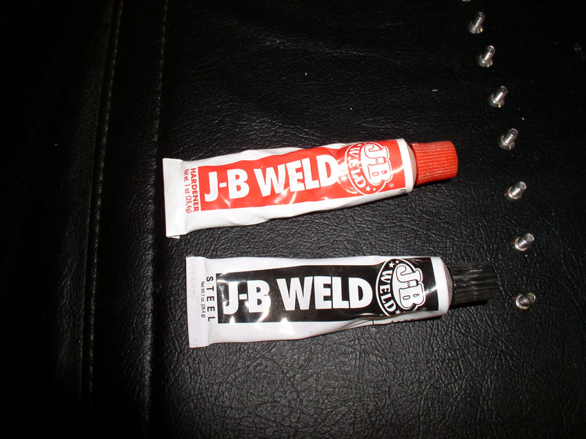
Here's the JB Weld I used. The instructions recommend using the longer setting
material (not the quick set type).
I cleaned the back of the insert with brake cleaning fluid....
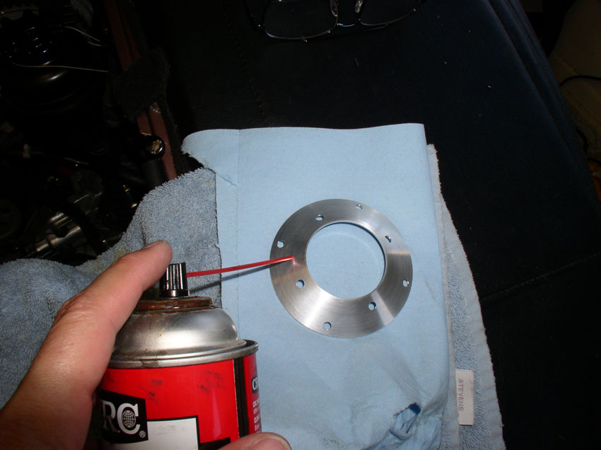
as well as the block surface....
...and wiped down with a clean rag.
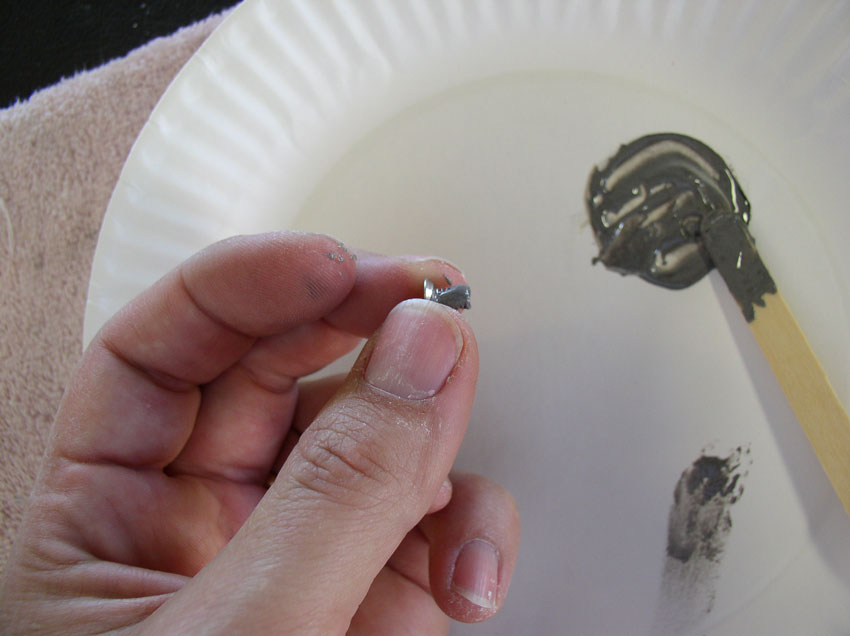
Mix equal amounts of steel compound and hardening agent as instructed.
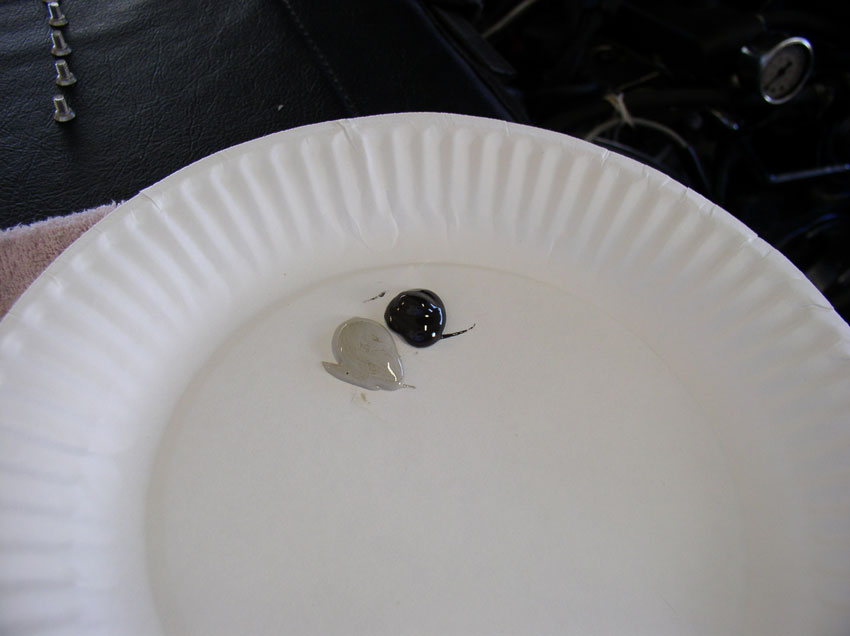
Mix until color is consistent.
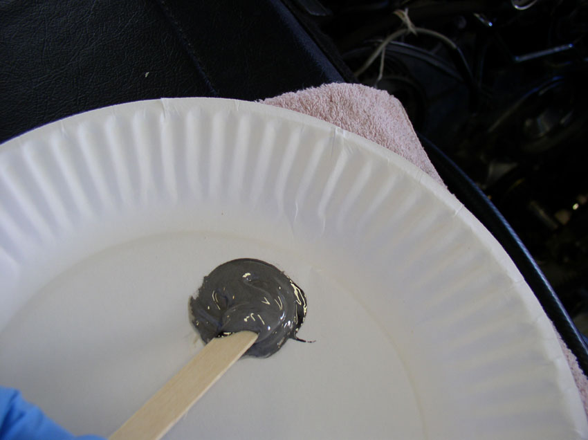
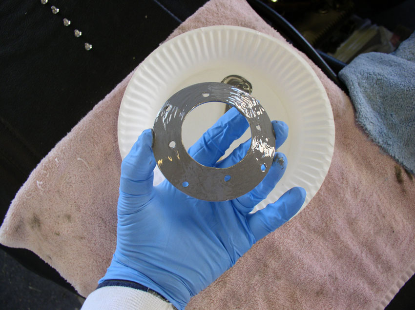
I used a popcicle stick to spread the JB Weld onto
the back of the insert.
Then spread it evenly with my finger.
Next, locate the insert to the same position it was located before removing and
applying JB Weld (i.e., locate the marking on the insert with the hole you
noted it matched to before removing the insert).
Start with the screw that goes with the marked hole on the insert.
Start installing the screws working your way clockwise.
For the screw that "communicates" with the outer block (for mine, it
was the
Then installed the screw.
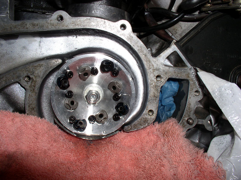
You should see a small amount of JB Weld oozing from the edges of the insert
and possibly a small amount from around the screw heads. This is normal. Simply
wipe up the excess.
When it's cleaned up, it should look something like this picture below.
Now, fit the WP gasket in place....
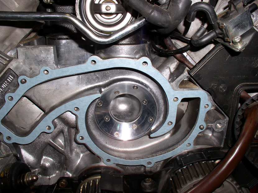
...and install the water pump.
Tighten the WP-to-block bolts to 7 ftlbs. Install all
bolts (except for the one that goes through the timing belt cover, of course).
Test for free movement of the TB pulley. In my case, it moved freely with no
scraping noise whatsoever.
At this point, you have finished the repair and can start reinstalling the
timing belt. It was at this point that I discovered that the tension applied by
the timing belt actually make the water pump give a very light scraping sound
for about 1/4 of a turn on each revolution of the impeller. When
I took the Timing belt off, no noise. So I decided slightly more
thickness was needed on the water pump gasket. There are two options, you can
apply water pump gasket sealant to both sides of the gasket or you can simply
install 2 gaskets dry. I opted for adding the sealant to both sides of the
gasket. Here's the water pump gasket sealant I used.

After I applied the gasket sealant, torqued down the
water pump, let it sit overnight to cure and reinstalled the timing belt, the
scraping noise was eliminated. At this point I proceeded to reassemble the
front of the engine, fill with coolant, check for leaks and start
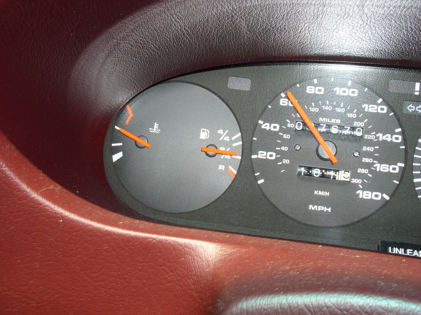
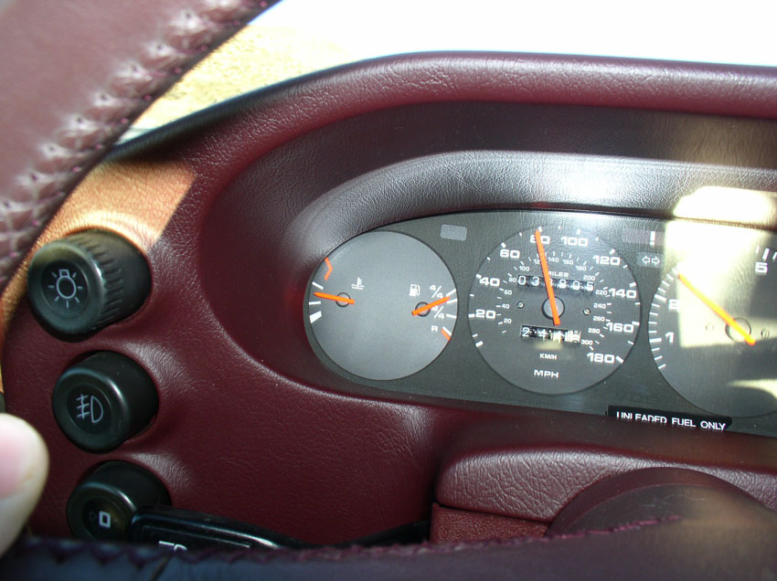
Here's the "after" pic same conditions
except for ambient temperature being about 70 degrees (and I was driving a
little faster - closer to 80). Therefore, it's not a true comparison before and
after and I'll have to wait until warmer temps to run the test again but so far
looks good.
I'd also like to thank Steve and Greg (Brown) for their efforts in developing
this tool for our community to use. It was a great experience and the tool is
designed very well. THANKS also to Greg (Nettles) for donating the air drill
for the job - it worked GREAT! THANK YOU all!
Please feel free to comment or add to this post as I'm happy to improve the
quality of this post - especially if I have missed something or incorrectly
described something. THANKS for reading!
Version: