OK...here's the pics from this mornings
work...
First of all, I followed Pirtle's writeup
step by step - So he gets the credit for putting all this down in the first
place. Made things go smooth.
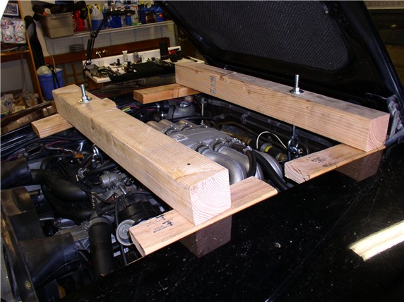
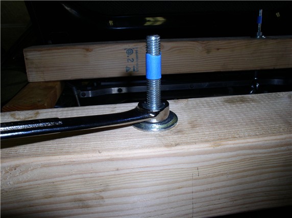
Last Weekend, I prefabricated the engine support using Andrew Olson's design.
Went to Home Depot and got a 4X4 and had them cut it to 35.25" and a 37.25" lengths. The 35.25" piece goes up front
and the 37.25" at the back of the engine. Also bought 1/2" X 10"
eye bolts (w/nuts) and large washers. All the parts were about $22. I cut some
scrap 2X4 into about 12" lenghts (4 of 'em) and counter sunk holes to fit over the fender bolt
heads/washers so the 2X4s would lay flush. I removed the hood shocks to make
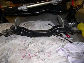
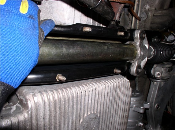
room for the 4X4. Here's what they look like on the car with the hardware
attached. THANKS again, Andew! ![]()
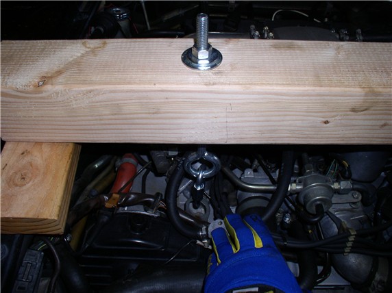
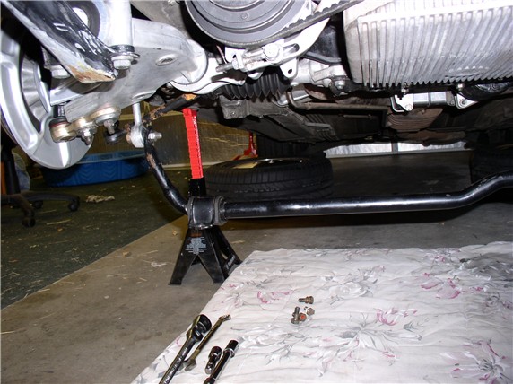
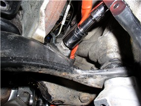
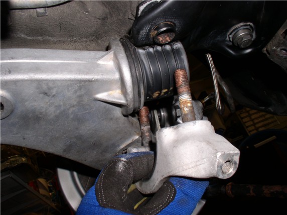
and here's where I connected the link's to the lift
point (front)
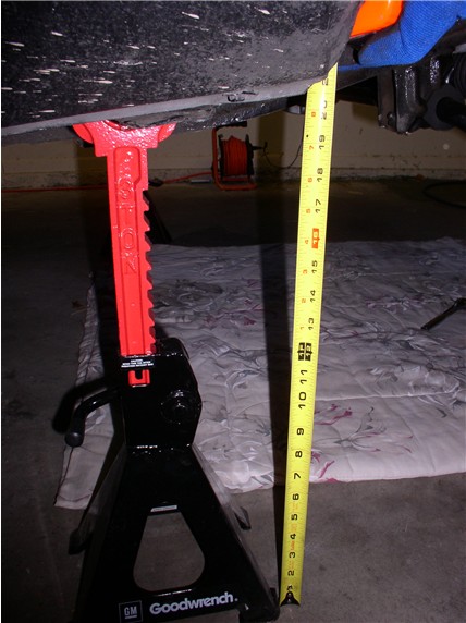
I disconnected the battery and raised the vehicle as high as possible. About 20" from floor to lift point.
I removed the front wheels next although it would have been easier to loosen
the lugs while weight was on wheels - so I had to use an impact wrench to get
the wheels off once off the ground. Then I took off the oil filter and removed
the 10mm bolt from the wiring harness.
Next, I loosend the 19mm bolts connecting the sway
bar to the drop links. I used a socket wrench with a very long hanele and made loosening bolts a lot easier.
I took off the sway bar to body bolts and swung the sway bar down.
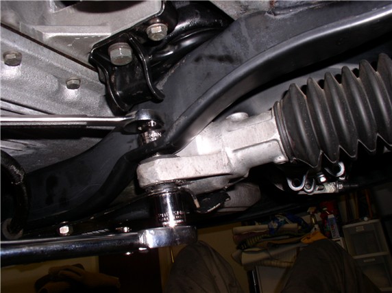
Next, I loosened the four 13mm nuts holding the steering rack plate to the
cross member
Then removed the 17mm bolt on the plate to the left of the steering rack
(driver's side)
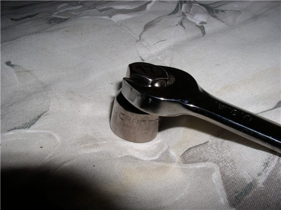
In order to
get at the four 17mm bolts/nuts holding the steering rack, I used a short
socket that came with the ratcheting wrenches. This worked great for getting
into the tight places above the rack to counter hold the bolts
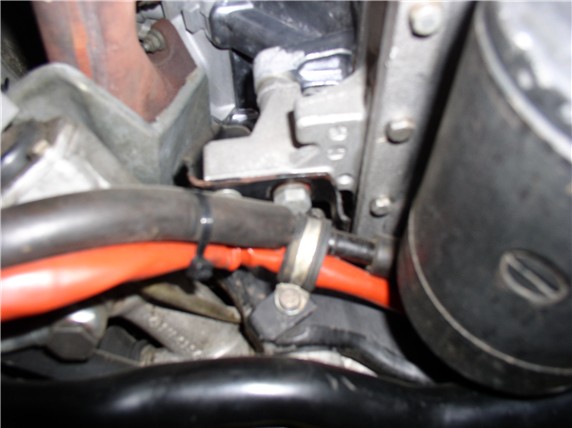
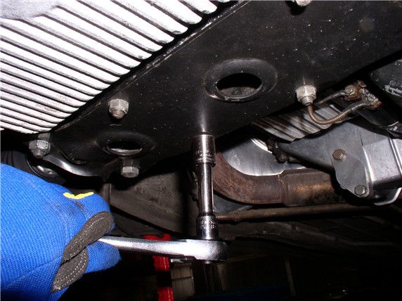
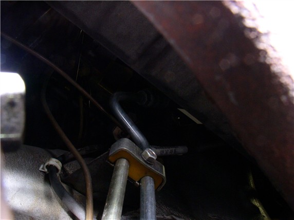
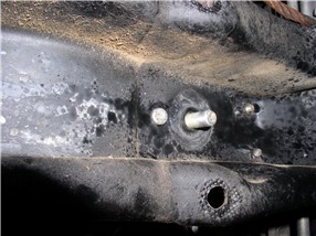
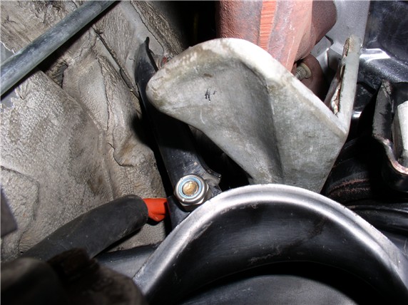
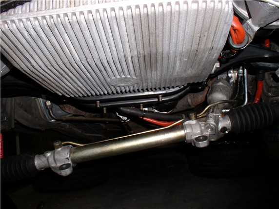
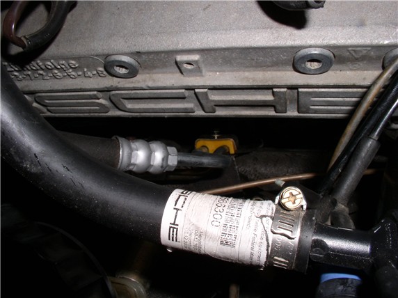
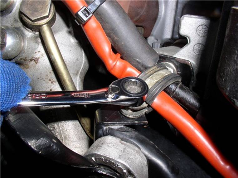
I added a step to Pirtle's process at this point.
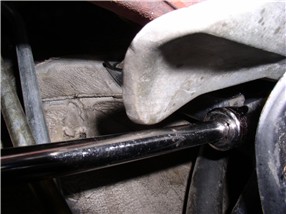
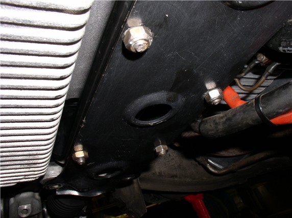
Before dropping the steering rack, I needed to take out the PS line clamp on
the driver's side fender - here's a picture of it - can be accessed either from
top or below. Just follow the PS steel lines from the rack up the side of the
engine bay and you should see it. I got to it from the top and used a 10mm
ratcheting wrench.
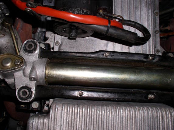
Next, I removed the four 13mm nuts holding the rack plate in place and removed
the steering rack plate.
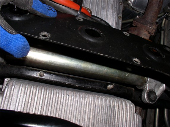
exposing the steering rack which can now be pulled
down and maneuvered around.
Then I loosened the 19mm nuts at the bottom of the motor mounts (under the
cross member)
And removed the 13mm and 17mm bolts that hold the mount housing to the engine
block
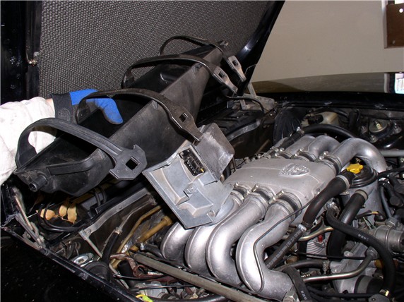
Next, I needed
to lift the engine - about an inch. I removed the air box (both upper and lower
halves when I put the 4X4 engine support across the engine compartment). I put
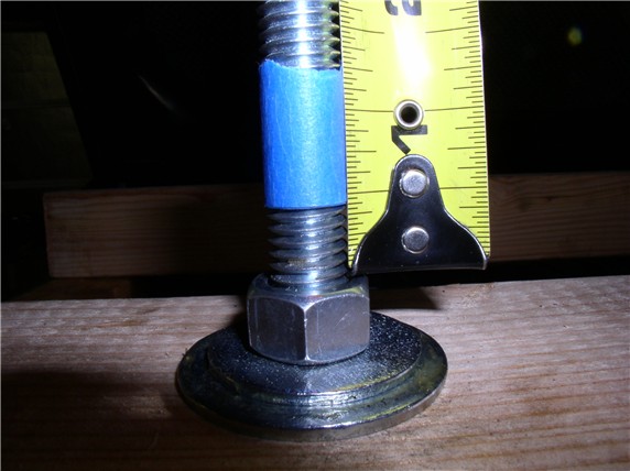
masking tape on the engine support bolt threads after snugging
the nut down by hand.
Then tightened the nut until 1" of thread was exposed below the tape - make
sure you check the clearance of the O2 sensor while lifting the engine. Mine
was OK.
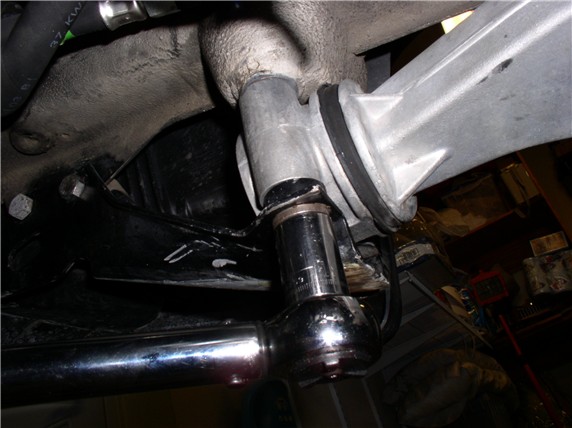
Next, I removed the lower motor mount nuts under the crossmember.
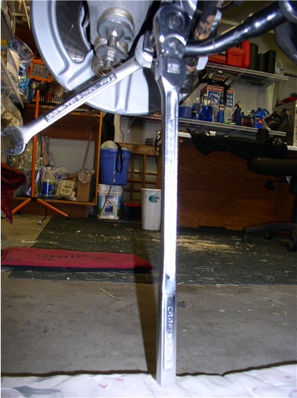
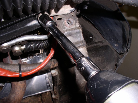
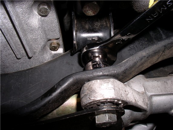
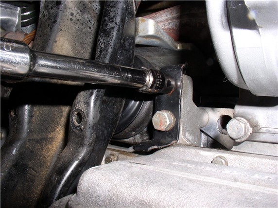
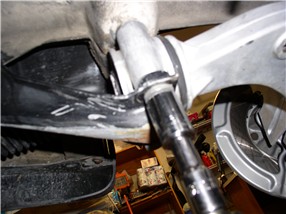
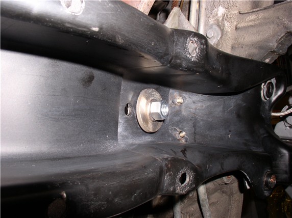
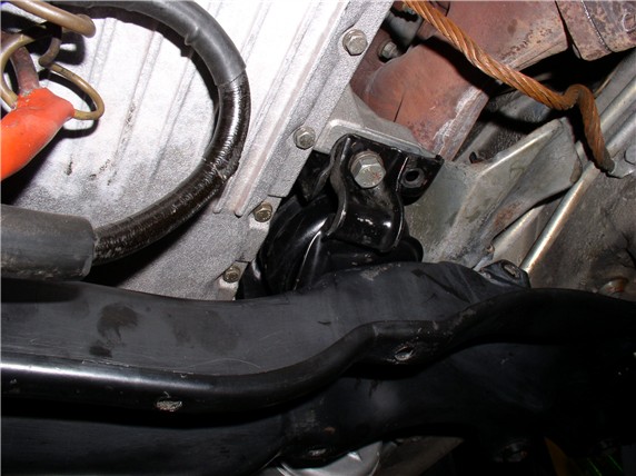
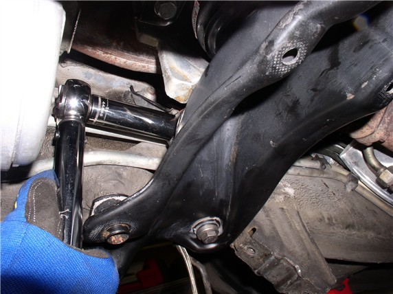
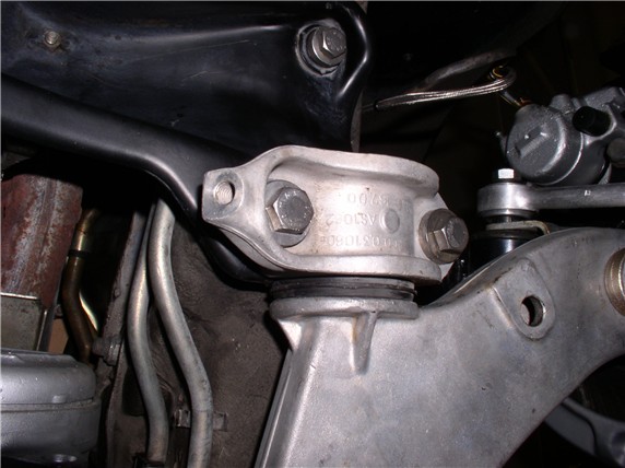
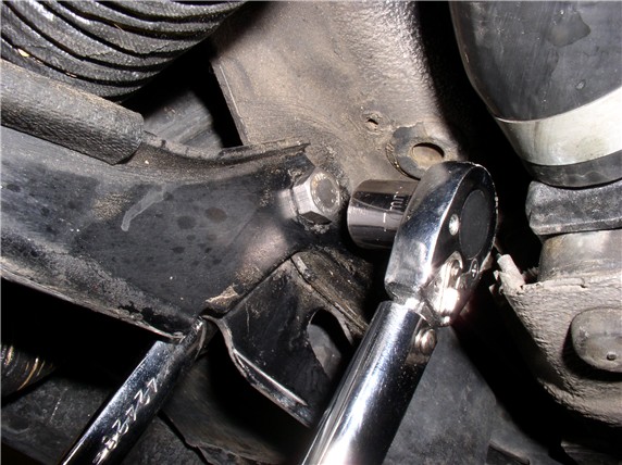
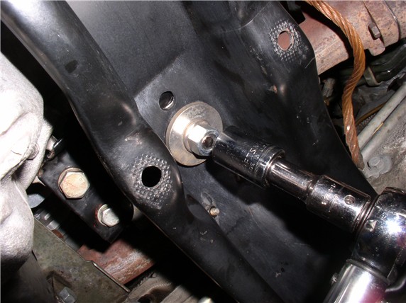
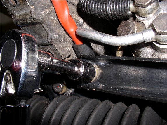
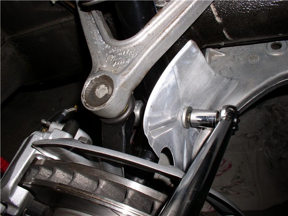
Then came the INFAMOUS crossmember upper support
bracket bolts. I was warned about these. Rather than counter hold the nut from
above in the engine compartment (as was suggested), I used a long socket
extension on the rearward nut (driver's side) and a regular socket for the
front. The passenger side did not seem to have space issues.
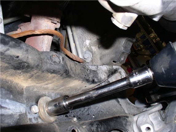
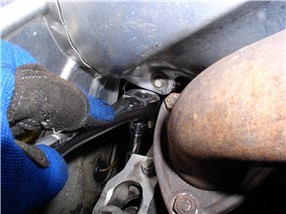
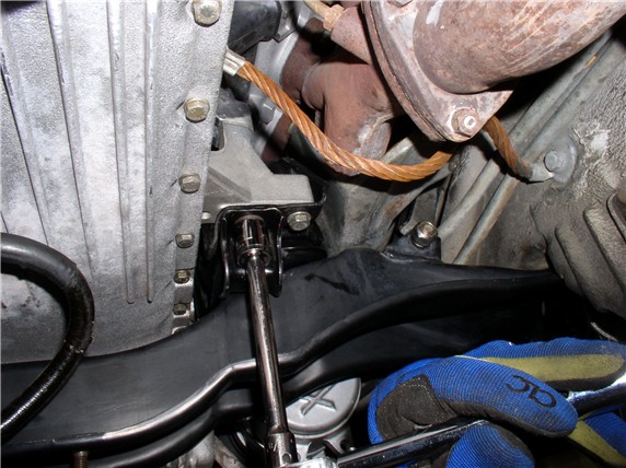
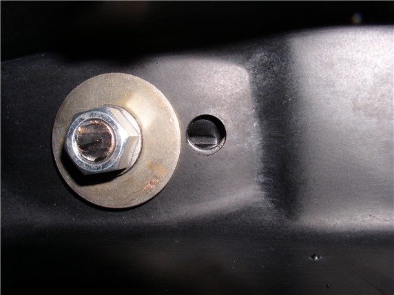
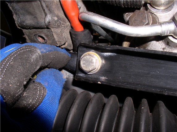
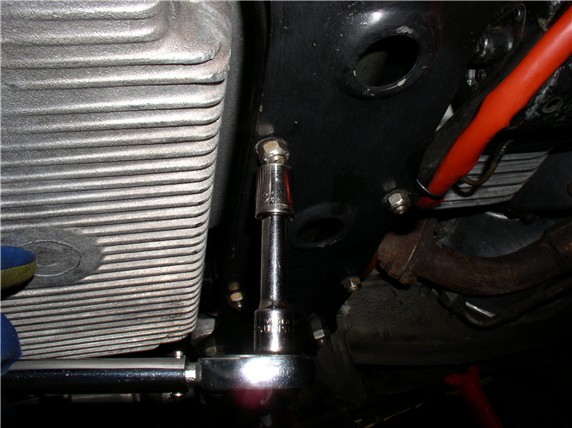
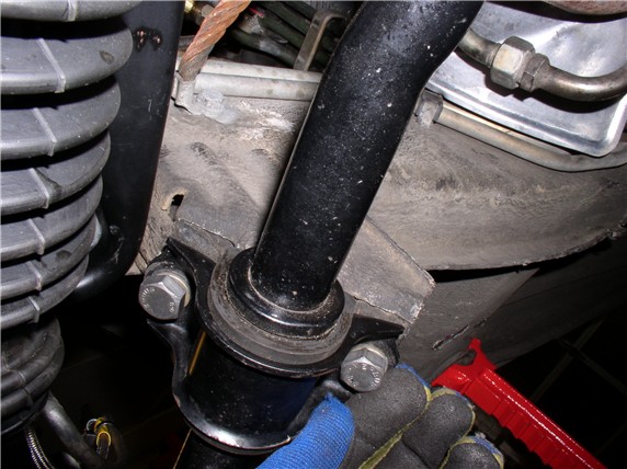
Here's the front bolt (driver's side):
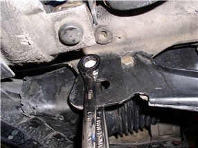
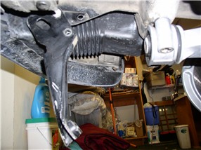
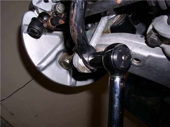
and the rear nut (driver's side) using a long extension
The driver's side come out easy by hand. But the Passenger side required
tapping with a hammer and screwdriver. This one will be interesting to get back
in.
Next, I loosened the front 17mm bolt on the tow hook at the front of the
chassis and removed the 2nd (rear) bolt.
Then I removed the two 19mm bolts at the end of the tow hook - these are the
two bolts used to mount the front of the Lower Control Arm as well.
The tow hook should then swing down freely.
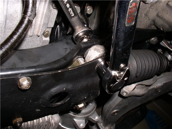
Next, I removed the two 19mm bolts at the rear of the control arm mounts
Finally, I removed the two 19mm bolts holding the cross member - one at each
end.
Then I maneuvered the crossmember down enough to
remove the motor mounts. Then some additional maneuving to get the crossmember
out completely.
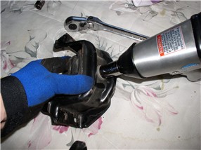
After the motor mounts were out, I used the air impact wrench to get the upper
bolt off the mount.
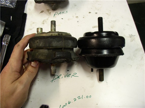
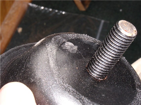
Then I compared the old and new mounts side by side and looked for differences.
The first obvious difference is mine's flattened. Second, it looks like I'll
have to grind off the little pin in the top of the mount. And it looks like no
pin to hold the mount in place while tightening on the new mount.
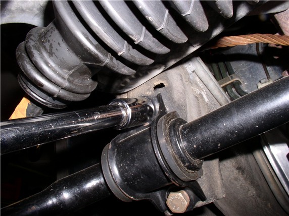
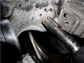
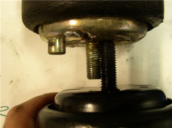
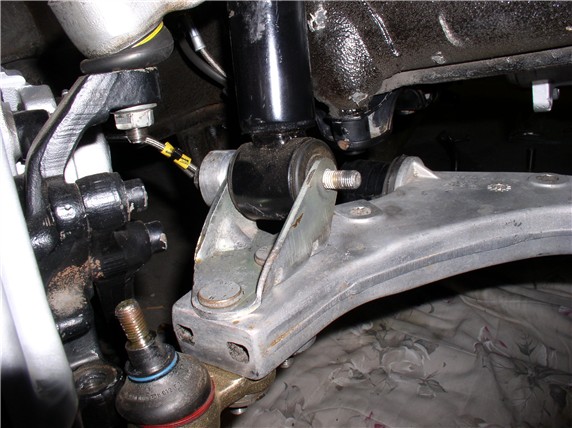
I also looked at the clearance I had between the lower motor mount stud and the
steering rack banjo bolts while the rack was in the car and noticed I would have
very little room left for a longer stud on the new mount. So
I compared stud lengths on the mounts and the new one is about 1/4" longer
(actually about 3/16"). So rather than take any chances, I'll
remove about 3/16" of the threads on the lower motor mount stud.
Well, that's as far as I got this morning before I broke for lunch and posted
these pics. Now it's back to work. I'll make the mods to the new mounts first. Then I'll do some cleaning -
I actually missed a couple of bolts and there are areas on the crossmember I couldn't get to before so now's
the perfect time to do some more cleaning before reassembly. It's
Here's some pics from the progress made late yesterday on the MM mods and initial reinstall.
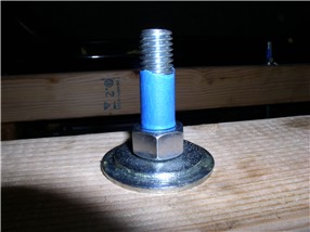
I used a dremel tool to cut the pin off the top of
the new MM - went quickly.
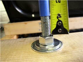
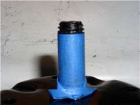
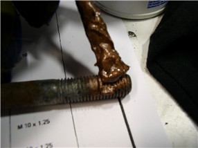
Next, I measured about 3/16" and taped the new MM lower stud so it would
be the same length as the original. The first one I used a grinding wheel to
grind it down - took about 15 minutes. The second I used the dremel - took about 5 minutes.
When I began the reinstallation, it started with bolting the top MM bracket to
the top MM stud and torquing it down to 62ftlb. Then getting the crossmember back into
position with the heat shields still attached. After struggling with it
for about 20 mintues with no progress, I decided to
disconnect the passenger lower control arm from the lower shock mount and
remove the sway bar as well. After that, the crossmember
was in position in about 5 minutes with no hassles.
With the cross member close to position, I tilted it back toward the rear
enough to insert/place the motor mounts (with bottom plate) bottom studs
through the hole in the crossmember. This was the
same way I took the MM out from the crossmember. I
kept the bottom plate lined up by aligning the pin hole in the bottom plate
with the alignment hole in the crossmember. Then put
the washers and 19MM nut on just enough to keep the MM from coming out.
At this point, I'm still holding up the crossmember.
Next I maneuvered the crossmember with mounts
attached up to the mounting holes in the engine block and placed the 17MM and
13MM bolts in and hand tightened. Now the crossmember
was held up and I could work on getting other bolts aligned and installed while
everything was loose.
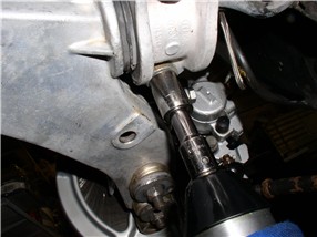
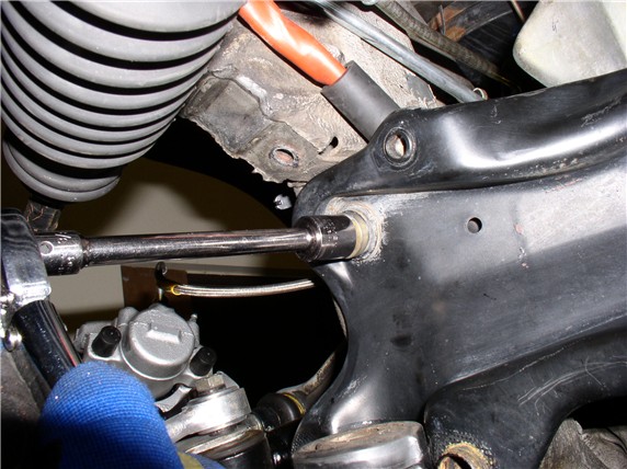
Next, I installed the INFAMOUS crossmember support
bracket 19MM bolt. I think the key to getting these back in is to do it when
everything is nice and loose. The driver's side when in
without a hitch - just pushed it in by hand. The passenger side needed a
slight pull with the prybar to line the holes and a
few taps with the hammer and it went right in. ![]() I did
not torque these down yet.
I did
not torque these down yet.
Then I placed the 17MM crossmember to frame bolts
(one at each end) and hand tightened. Then I went back and torqued
the bolts in. Started with the MM bracket to engine block
17MM (33ftlb) and 13MM (17ftlb).
Next, I torqued the crossmember
to frame 17MM bolts (one at each end - 33ftlb).
And finally, I torqued the crossmember
support bracket 19MM bolts (62ftlb).
That's as far as I got last night. So far, time on task working on disassembly
and reinstallation only has been about 6.5 hours. Three more hours on top of
that for cleaning and setting up the grinder. Now it's about
Started at
So here's the rest of the pics
for the remaining install I did today...
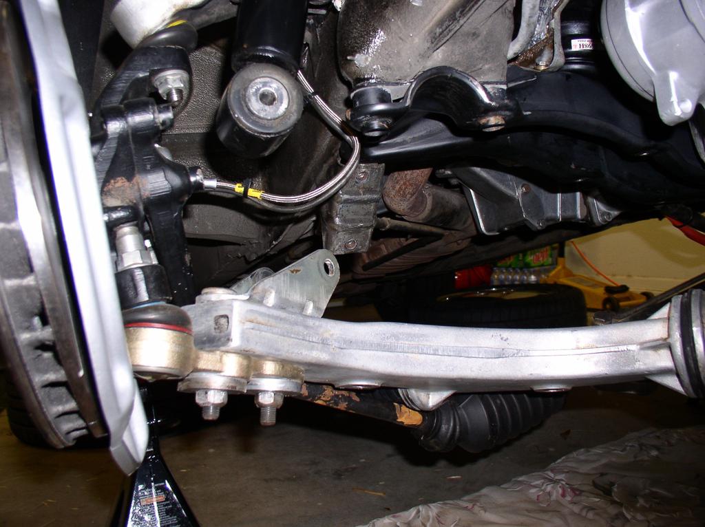
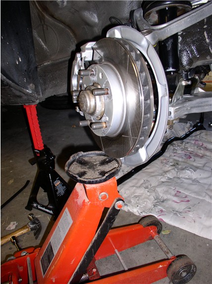
Since I removed the LCA to get the crossmember back
in, I had struggled with getting the lower shock mount to line up with the LCA
bracket - too many things under tension. So this morning I tried a different
approach and used the floor jack to hold up the hub/upper ctl
arm while I maneuvered the LCA into place. Took about 10 min.
All I did at this point was insert the bolt with the stabilizer link on the
back side to hold things in place while I re-inserted the lower ball joint stud
in the steering knuckle.
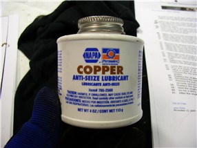
The WSM recommends applying Optimoly HT (Copper
Anti-Freeze, er Anti-SEIZE) to the Lower control arm
bolts before putting them back in (both forward and rear LCA bolts)
This is what I'm using for Optimoly HT:
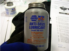
And this is what I use for Optimoly TA (Aluminum
colored anti-seize):
I installed the rear LCA bracket first:
I only tighten the 19MM bolts 'til there's about 1/8" gap between the
bracket and the crossmember. I read that this will
allow the car to settle easier after weight on wheels and a short drive. Then I
torque it down after the car settles:
Then I installed the front 19MM LCA bolts along with the tow eye/guard bracket.
These are torqued at this time 62ftlb.
Next, I re-installed the 17MM tow eye/guard bolt up front and torqued it down along with the front bolt - 33ftlb.
At this point, I lowered the engine. I had raised the engine 1 inch before the
install (marked by the tape)
After I lowered the engine, I measured the new engine height resulting from the
new mounts. Looks like it raised the engine about 1/2".
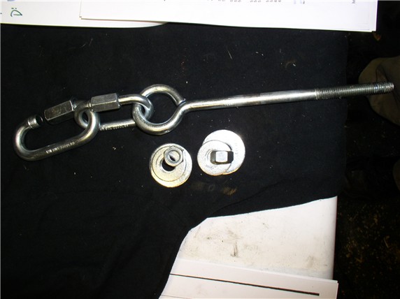
I removed the 4X4s and 2X4s. Someone asked what links
I used for the engine support. The eye bolt is 10" long and 1/2"
threads. These links are rated at over 2000lb for the small and over 3000lb for
the large.
After lowering
the engine, I torqued down the 19MM lower motor mount
bolt - 62ftlb.
I also made sure the alignment holes were lined up. Normally there would be a
pin here on the Porsche mounts to keep the upper and lower mount bracket
fingers aligned.
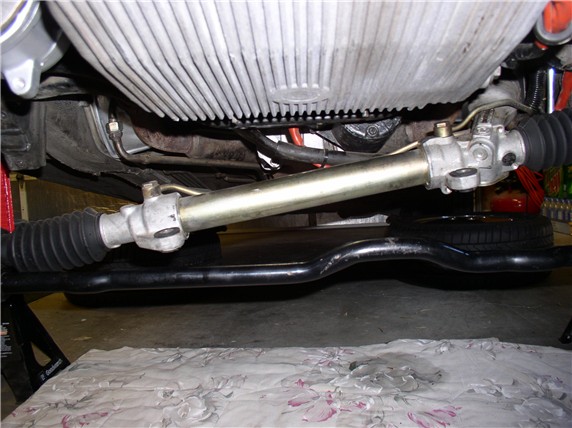
Next came the steering rack. Put the four 13MM locking
studs in the crossmember from the top.
I maneuvered the rack back into the crossmember
channel and held it with one had while getting the reiforcement
plate lined up with the 13MM studs.
Then hand-tighten the four 13MM bolts to hold the plate in place
Next, I installed the single short 17MM bolt at the end of the reinforcement
plate (hand tightened only so that the remaining four Steering rack 17MM bolts
could be lined up and assembled).
Then I installed the four 17MM steering rack bushing bolts and torqued them down - 33ftlb
Next, Torqued the single short 17MM bolt at the end
of the plate - 33ftlb
And finally, torqued the four 13MM plate nuts -
17ftlb
To finish off the steering, I then re-attached the PS line clamp to the side of
the engine compartment. Best to reach this from the top using
a 10mm ratchet wrench.
Next in order
was the starter wiring harness. Just a 10MM bolt here...
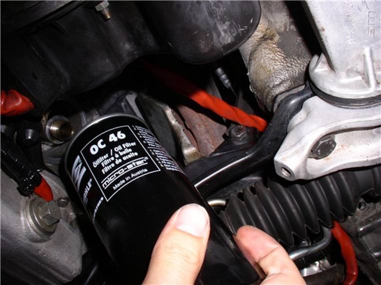
Then I installed the oil filter
The sway bar was next. I only tightened these until
they were snug. Again, I read that leaving these un-torqued
until the car settles is better. I just replaced the frame bushings last month
but still want to lubricate them. I didn't have time to find bushing lube (WSM
recommended MolyKote U - aka
dry graphite molybdenum disulphide - THANKS Wally for the fancy name! - I love
asking for this stuff at the local auto parts store - I just get blank stares ![]() ) I will
find a supplier soon and lube them up next time they are out - which won't be
long - I'm sure.
) I will
find a supplier soon and lube them up next time they are out - which won't be
long - I'm sure.
Then I torqued the 19MM stabilizer link bolts at the
stabilizer bar - 62ftlb
Next I torqued the 19MM lower shock mount to Lower
Control Arm and stabilizer link Bolt - 62ftlb
Then I replaced the air box and hooked up the air filter and air tubes.
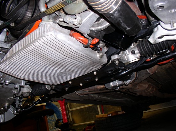
All done underneath....
At this point, I would have put the tires back on and lowered the car, put the
engine cross brace back on, topped off the oil, and started it up. But I wanted
to check a couple other things while the car was in the air - the flex plate
tension (since I effectively raised the engine 1/2" with the new mounts)
and the crank shaft end play - more on that later.
After taking the car for a drive to let the suspension settle, I brought it
back and drove it up on ramps and did the final torque on the Lower Control Arm
rear mounts - 19MM and they are torqued to 88ftlb. Also torqued the stabilizer frame bushing
bolts - 17MM torqued to 33ftlb. Took a final
drive and DONE! and WOW...I like the new mounts!!
THANKS to all that posted on doing this job before - I learned alot before even turning a wrench on this one ![]()
![]()
![]() ....and
thanks to Pirtle for documenting the procedure!
....and
thanks to Pirtle for documenting the procedure! ![]()
![]()
![]()